
64-bit Intel Xeon Processorwith up to 8MB L3 Cache Thermal/Mechanical Design Guidelines


R
4 64-bit Intel
®
Xeon™ Processor MP with 8 MB L3 Cache
Thermal/Mechanical Design Guidelines
Figures
2-1 Critical Interface Dimensions (Sheet 1 of 2) ........................................................ 10
2-2 Critical Interface Dimensions (Sheet 2 of 2) ........................................................ 11
2-3 Thermal Profile Diagram ...................................................................................... 12
2-4 T
CONTROL
and Thermal Profile Interaction ............................................................. 13
2-5 Thermal Profile for the 64-bit Intel
®
Xeon™ Processor MP
with 8 MB L3 Cache............................................................................................. 14
2-6 T
CONTROL
and Fan Speed Control ......................................................................... 15
2-7 Processor Thermal Characterization Parameter Relationships........................... 17
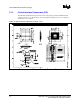
2-8 Exploded View of Cooling Solution Thermal Solution Components .................... 21
2-9 2U+ Cooling Solution Heatsink Thermal Performance ........................................ 22
2-10 Isometric View of the 2U+ Cooling Solution Heatsink ......................................... 23
2-11 Hat Spring Isometric View.................................................................................... 25
2-12 Isometric View of Hat Spring Attachment to the Base Board .............................. 25
A-1 2U Cooling Solution Heatsink (Sheet 1 of 4) ....................................................... 28
A-2 2U Cooling Solution Heatsink (Sheet 2 of 4) ....................................................... 28
A-3 2U Cooling Solution Heatsink (Sheet 3 of 4) ....................................................... 29
A-4 2U Cooling Solution Heatsink (Sheet 4 of 4) ....................................................... 29
A-5 Cooling Solution Hat Spring (Sheet 1 of 3).......................................................... 30
A-6 Cooling Solution Hat Spring (Sheet 2 of 3).......................................................... 30
A-7 Cooling Solution Hat Spring (Sheet 3 of 3).......................................................... 31
A-8
Baseboard Keepout Footprint Definition and Height Restrictions for
Enabling Components (Sheet 1 of 5)................................................................... 32
A-9
Baseboard Keepout Footprint Definition and Height Restrictions for
Enabling Components (Sheet 2 of 5)................................................................... 33
A-10
Baseboard Keepout Footprint Definition and Height Restrictions for
Enabling Components (Sheet 3 of 5)................................................................... 34
A-11
Baseboard Keepout Footprint Definition and Height Restrictions for
Enabling Components (Sheet 4 of 5)................................................................... 34
A-12
Baseboard Keepout Footprint Definition and Height Restrictions for
Enabling Components (Sheet 5 of 5)................................................................... 35
B-1 IHS Groove .......................................................................................................... 38
B-2 Groove to Pin Indicator ........................................................................................ 39
B-3 IHS Groove .......................................................................................................... 39
B-4 Bending Tip of Thermocouple.............................................................................. 40
B-5 Securing Thermocouple Wires with Kapton* Tape .............................................. 41
B-6 Thermocouple Bead Placement........................................................................... 41
B-7 Thermocouple Placement .................................................................................... 41
B-8 3D Micromanipulator to Secure Bead Location ................................................... 42
B-9 Measuring Resistance between Thermocouple and IHS .................................... 42
B-10 Applying the Adhesive on the Thermocouple Bead............................................. 42
B-11 Thermocouple Wire Management in the Groove................................................. 43
B-12 Removing Excess Adhesive from the IHS ........................................................... 44
B-13 Filling the Groove with Adhesive.......................................................................... 44
B-14 Thermocouple Wire Management........................................................................ 45
B-15 Local Air Thermocouple Placement for Passive Heatsinks ................................. 45
B-16 Local Air Thermocouple Placement for Active Heatsinks (Side View) ................ 46
B-17 Local Air Thermocouple Placement for Active Heatsinks (Plan View) ................ 46
D-1 Random Vibration PSD........................................................................................ 49
D-2 Shock Acceleration Curve.................................................................................... 50