
64-bit Intel Xeon Processorwith 1MB L2 Cache Thermal/Mechanical Design Guidelines


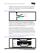
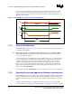
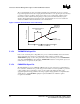
Table Of Contents
Processor Thermal Management Logic and Thermal Monitor Features
R
56 64-bit Intel
®
Xeon™ Processor MP with 1 MB L2 Cache
Thermal/Mechanical Design Guidelines
temperature. By comparing this current with the reference current, the processor temperature can be
determined. The reference current source corresponds to the diode current when at the maximum
permissible processor operating temperature. Processors are calibrated during manufacturing on a
small sample set. Once configured, the processor temperature at which the PROCHOT# signal is
asserted (trip point) is not re-configurable.
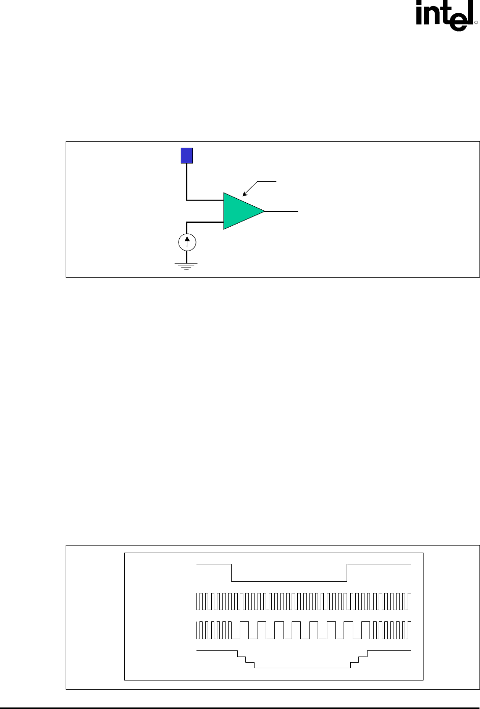
Figure F-1. Thermal Sensor Circuit
PROCHOT#
Temperature Sensing Diode
Reference Current Source
Current Comparator
The PROCHOT# signal is available internally to the processor as well as externally. External
indication of the processor temperature status is provided through the bus signal PROCHOT#.
When the processor temperature reaches the trip point, PROCHOT# is asserted. When the processor
temperature is below the trip point, PROCHOT# is de-asserted. Assertion of the PROCHOT# signal
is independent of any register settings within the processor. It is asserted any time the processor die
temperature reaches the trip point. The point where the TCC activates is set to the same temperature
at which the processor is tested and at which PROCHOT# asserts.
The TCC portion of the Thermal Monitor must be enabled for the processor to operate within
specifications. The Thermal Monitor’s TCC, when active, lowers the processor temperature by
reducing the power consumed by the processor. This is done by changing the duty cycle of the
internal processor clocks, resulting in a lower effective frequency. When active, the TCC turns the
processor clocks off and then back on with a predetermined duty cycle. The duty cycle is processor
specific, and is fixed for a particular processor. The maximum time period the clocks are disabled is
~3 µs, and is frequency dependent. Higher frequency processors will disable the internal clocks for a
shorter time period. Figure F-2 illustrates the relationship between the internal processor clocks and
PROCHOT#.
Performance counter registers, status bits in model specific registers (MSRs), and the PROCHOT#
output pin are available to monitor and control the Thermal Monitor behavior.
Figure F-2. Concept for Clocks under Thermal Monitor Control
PROCHOT#
N
ormal cloc
k
Core clock w/
TM2 Engaged
VID w/ TM2
Engaged