
64-bit Intel Xeon Processorwith 1MB L2 Cache Thermal/Mechanical Design Guidelines
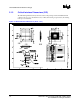
Table Of Contents

R
4 64-bit Intel
®
Xeon™ Processor MP with 1 MB L2 Cache
Thermal/Mechanical Design Guidelines
F
Processor Thermal Management Logic and Thermal Monitor Features................... 55
F.1
Thermal Management Logic and Thermal Monitor Feature ................................ 55
F.1.1
Processor Power Dissipation .................................................................. 55
F.1.2
Thermal Monitor Implementation ............................................................ 55
F.1.3
Operation and Configuration................................................................... 57
F.1.4
Thermal Monitor 2................................................................................... 57
F.1.5
System Considerations ........................................................................... 58
F.1.6
Operating System and Application Software Considerations ................. 58
F.1.7
Legacy Thermal Management Capabilities ............................................ 59
F.1.8
Cooling System Failure Warning ............................................................ 61
Figures
2-1 Critical Interface Dimensions (Sheet 1 of 2) ........................................................ 10
2-2 Critical Interface Dimensions (Sheet 2 of 2) ........................................................ 11
2-3 Thermal Profile Diagram ...................................................................................... 12
2-4 T
CONTROL
and Thermal Profile Interaction ............................................................. 13
2-5 Thermal Profile for the 64-bit Intel
®
Xeon™ Processor MP
with 1 MB L2 Cache............................................................................................. 14
2-6 T
CONTROL
and Fan Speed Control ......................................................................... 15
2-7 Processor Thermal Characterization Parameter Relationships........................... 17
2-8 Exploded View of Cooling Solution Thermal Solution Components .................... 21
2-9 2U+ Cooling Solution Heatsink Thermal Performance ........................................ 22
2-10 Isometric View of the 2U+ Cooling Solution Heatsink ......................................... 23
2-11 Hat Spring Isometric View.................................................................................... 25
2-12 Isometric View of Hat Spring Attachment to the Base Board .............................. 25
A-1 2U Cooling Solution Heatsink (Sheet 1 of 4) ....................................................... 28
A-2 2U Cooling Solution Heatsink (Sheet 2 of 4) ....................................................... 28
A-3 2U Cooling Solution Heatsink (Sheet 3 of 4) ....................................................... 29
A-4 2U Cooling Solution Heatsink (Sheet 4 of 4) ....................................................... 29
A-5 Cooling Solution Hat Spring (Sheet 1 of 3).......................................................... 30
A-6 Cooling Solution Hat Spring (Sheet 2 of 3).......................................................... 30
A-7 Cooling Solution Hat Spring (Sheet 3 of 3).......................................................... 31
A-8
Baseboard Keepout Footprint Definition and Height Restrictions for
Enabling Components (Sheet 1 of 5)................................................................... 32
A-9
Baseboard Keepout Footprint Definition and Height Restrictions for
Enabling Components (Sheet 2 of 5)................................................................... 33
A-10
Baseboard Keepout Footprint Definition and Height Restrictions for
Enabling Components (Sheet 3 of 5)................................................................... 34
A-11
Baseboard Keepout Footprint Definition and Height Restrictions for
Enabling Components (Sheet 4 of 5)................................................................... 34
A-12
Baseboard Keepout Footprint Definition and Height Restrictions for
Enabling Components (Sheet 5 of 5)................................................................... 35
B-1 IHS Groove .......................................................................................................... 38
B-2 Groove to Pin Indicator ........................................................................................ 39
B-3 IHS Groove .......................................................................................................... 39
B-4 Bending Tip of Thermocouple.............................................................................. 40
B-5 Securing Thermocouple Wires with Kapton* Tape .............................................. 41
B-6 Thermocouple Bead Placement........................................................................... 41
B-7 Thermocouple Placement .................................................................................... 41
B-8 3D Micromanipulator to Secure Bead Location ................................................... 42