
64-bit Intel Xeon Processorwith 1MB L2 Cache Thermal/Mechanical Design Guidelines
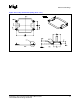
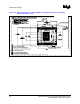
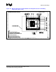
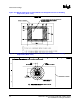
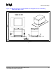
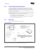
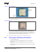
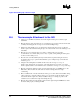
Table Of Contents
R
Testing Methods
64-bit Intel
®
Xeon™ Processor MP with 1 MB L2 Cache 39
Thermal/Mechanical Design Guidelines
Figure B-2. Groove to Pin Indicator
When the processor is installed in the socket, the groove is perpendicular to the socket load lever,
and on the opposite side of the lever.
Figure B-3. IHS Groove
Select a machine shop that is capable of holding drawing specified tolerances. IHS channel
geometry is critical for repeatable placement of the thermocouple bead, ensuring precise thermal
measurements. The specified dimensions minimize the impact of the groove on the IHS under the
socket load. A larger groove may cause the IHS to warp under the socket load such that it does not
represent the performance of an ungrooved IHS on production packages.
Note: Inspect parts for compliance to specifications before accepting from machine shop.
B.5 Thermocouple Conditioning and Preparation
1. Use a calibrated thermocouple.
2. Measure the thermocouple resistance by holding both wires on one probe and the tip of
thermocouple to the other probe of the DMM (compare to thermocouple resistance
specifications).
3. Straighten the wire for about 38 mm [1 inch] from the bead to place it inside the channel.
4. Bend the tip of the thermocouple at approximately 45 degree angle by about 0.8 mm [0.030
inch] from the tip.