
64-bit Intel Xeon Processorwith 1MB L2 Cache Thermal/Mechanical Design Guidelines
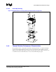
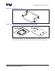
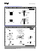
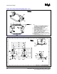
Table Of Contents

R
Thermal/Mechanical Reference Design
64-bit Intel
®
Xeon™ Processor MP with 1 MB L2 Cache 23
Thermal/Mechanical Design Guidelines
2.4.7 Components Overview
2.4.7.1 Heatsink with Captive Screws and Standoffs
The cooling solution reference heatsink uses snapped-fin technology for its design. It consists of a
copper base and copper fins with Shin-Etsu* G751 thermal grease as the TIM. The mounting screws
and standoffs are also made captive to the heatsink base for ease of handling and assembly as shown
in Figure 2-10.
Figure 2-10. Isometric View of the 2U+ Cooling Solution Heatsink
NOTE: Refer to Appendix A for more detailed mechanical drawings of the heatsink.
The function of the standoffs is to provide a bridge between the chassis and the heatsink for
attaching and load carrying. When assembled, the heatsink is rigid against the top of the standoff,
and the standoff is rigid to a chassis standoff with the hat spring firmly sandwiched between the
two. In dynamic loading situations the standoffs carry much of the heatsink load, especially in
lateral conditions, when compared to the amount of load transmitted to the processor package. As
such, it is comprised of steel. The distance from the bottom of the heatsink to the bottom of the
standoff is 1.02 cm [0.402 in.].
The function of the screw is to provide a rigid attach method to sandwich the entire cooing solution
assembly together, activating the hat spring under the baseboard, and thus providing the TIM
preload. A screw is an inexpensive, low profile solution that does not negatively impact the thermal
performance of the heatsink due to air blockage. Any fastener (i.e. head configuration) can be used
as long as it is of steel construction; the head does not interfere with the heatsink fins, and is of the
correct length of 1.27 cm [0.50 in.].
Although the cooling solution heatsink fits into the legacy volumetric keep-in, it has a larger
footprint due to the elimination of retention mechanism and clips used in the older enabled
thermal/mechanical components. This allows the heatsink to grow its base and fin dimensions,
further improving the thermal performance. A drawback of this enlarged size and use of copper for
both the base and fins is the increased weight of the heatsink. The cooling solution heatsink is
estimated to weigh twice as much as previous heatsinks used with Intel Xeon processors. However,
the retention scheme employed by cooling solution is designed to support heavy heatsinks
(approximately up to 1000 grams) in cases of shock, vibration and installation as explained in
Appendix D.