
64-bit Intel Xeon Processorwith 1MB L2 Cache Thermal/Mechanical Design Guidelines
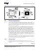
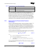
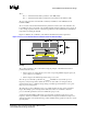
Table Of Contents

Thermal/Mechanical Reference Design
R
20 64-bit Intel
®
Xeon™ Processor MP with 1 MB L2 Cache
Thermal/Mechanical Design Guidelines
All thermal interface materials should be sized and positioned on the heatsink base in a way that
ensures the entire processor IHS area is covered. It is important to compensate for heatsink-to-
processor attach positional alignment when selecting the proper TIM size.
When pre-applied material is used, it is recommended to have a protective application tape over it.
This tape must be removed prior to heatsink installation.
The TIM performance is susceptible to degradation (i.e. grease breakdown) during the useful life of
the processor due to the temperature cycling phenomena. For this reason, the measured T
CASE
value
of a given processor can decrease over time depending on the type of TIM material.
2.4.3 Summary
In summary, considerations in heatsink design include:
• The local ambient temperature T
LA
at the heatsink, airflow (CFM), the power being
dissipated by the processor, and the corresponding maximum T
CASE
. These parameters are
usually combined in a single lump cooling performance parameter, Ψ
CA
(case to air thermal
characterization parameter). More information on the definition and the use of Ψ
CA
is given
in Section 1.4 and Section 2.3.2.
• Heatsink interface (to IHS) surface characteristics, including flatness and roughness.
• The performance of the TIM used between the heatsink and the IHS.
• Surface area of the heatsink.
• Heatsink material and technology.
• Development of airflow entering and within the heatsink area.
• Physical volumetric constraints placed by the system.
2.4.4 Assembly Overview of the Intel Reference Thermal
Mechanical Design
The 2U+ cooling solution consists of the following components:
• Heatsink (with captive standoff and screws)
• Thermal Interface Material (TIM-2)
• Hat Spring
2.4.4.1 Geometric Envelope
The baseboard keepout zones on the primary and secondary sides and height restrictions under the
enabling component region are shown in detail in Appendix A. The overall volumetric keep in zone
encapsulates the processor, socket, and the entire thermal/mechanical enabling solution.