
603 Pin Socket Design Guidelines

603 Pin Socket Design Guidelines
R
18
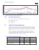
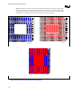
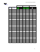
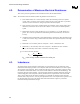
Figure 4-3 shows the resistance test fixtures separately and superimposed. The upper left figure (blue
traces) is the interposer. The upper right figure(red traces) is the baseboard. There are 31 daisy chain
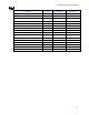
configurations on resistance test board. The bottom center view is the two pa1ts superimposed. Table
4-3 shows these configurations with the number of pins per each chain and netlist.
A
E
A
D
A
C
A
B
A
A
1
2
27
26
3
4
5
6
7
8
9
10
11
12
13
14
15
16
17
18
19
20
21
22
23
24
25
31
30
28
29
A
BCD EFGH
J
K
L
M
NPRTUV Y
W
1
2
27
26
3
4
5
6
7
8
9
10
11
12
13
14
15
16
17
18
19
20
21
22
23
24
25
31
30
28
29
ABCD
E
FG
HJ
K
L
M
N
P
R
T
U
V
Y
A
E
A
D
A
C
A
B
A
A
W
Figure 4-3: Electrical Resistance Fixtures superimposed.
1
A
B
2
27
26
AE
AD
C
D
E
F
G
H
J
K
L
M
N
P
R
T
U
V
Y
AC
AB
AA
3
4
5
6
7
8
9
10
11
12
13
14
15
16
17
18
19
20
21
22
23
24
25 31
30
28
29
W