
603 Pin Socket Design Guidelines

603 Pin Socket Design Guidelines
R
14
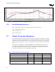
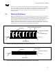
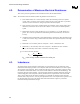
Figure 3-1: Typical Reflow Profile for 63Sn/37Pb solder
3.6.3. Overall Assembly Sequence:
Step 1 - Mount 603 Pin Socket to the motherboard using a surface mount process
Step 2 - Install retention mechanism
Step 3 - Install processor
Step 4 - Install heat sink
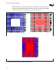
3.7. Critical To Function Dimensions:
The 603 Pin Socket shall accept a 603 pin processor pin field. All dimensions are Metric. Asymmetric
features are designed to properly align the socket to the motherboard and prevent the socket from being
assembled incorrectly to the motherboard. The socket dimensions are shown in Figure 9-4 (Appendix
A.4) and Figure 9-5 (Appendix A.5). Figure 9-2 (Appendix A.2) shows the outline of the processor pin
field.
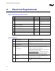
Critical to function dimensions are identified in Table 3-1. Each of the dimensions must meet the
requirements given in Table 3-1. These dimensions will be verified as part of the validation process.
Also, supplier will provide and maintain Critical Process Parameters controlling these CTFs or will
provide direct measurements to meet ongoing quality requirements.
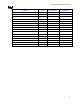
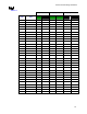
Table 3-1: Socket Critical To Function Dimensions
Dimension Index Minimum mm Maximum mm
Socket Length 63.75
Socket Width 53.70 54
Socket Height (Interposer surface from MB) 5.38 6.15
Assembled Cover Flatness N/A 0.20
Co-planarity
Lead / Surface Mount Feature
N/A
0.15