
VRM 9.1 DC-DC Converter Design Guidelines
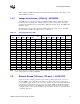
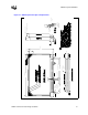
Table Of Contents
- 1 Electrical Specifications
- 1.1 Output Requirements
- 1.1.1 Voltage and Current - REQUIRED
- 1.1.2 Maximum Ratings - EXPECTED
- 1.1.3 Output Voltage Tolerance - REQUIRED
- 1.1.4 No-Load Operation - REQUIRED
- 1.1.5 Turn-on Response Time - EXPECTED
- 1.1.6 Overshoot and Undershoot at Turn-On or Turn-Off - REQUIRED
- 1.1.7 Converter Stability - REQUIRED
- 1.1.8 Current Sharing - REQUIRED
- 1.2 Input Voltage and Current
- 1.3 Control Inputs - REQUIRED
- 1.4 Remote Sense (VO-sen+, VO-sen-) - EXPECTED
- 1.5 Power Good Output (PWRGD) - REQUIRED
- 1.6 VRM Present (VRM-pres) - EXPECTED
- 1.7 Efficiency - PROPOSED
- 1.8 Isolation - PROPOSED
- 1.9 Fault Protection
- 1.1 Output Requirements
- 2 Module Layout Guidelines
- 3 Environmental Conditions
- 3.1 Operating Temperature - PROPOSED
- 3.2 VRM Board Temperature - REQUIRED
- 3.3 Non-Operating Temperature - PROPOSED
- 3.4 Humidity - PROPOSED
- 3.5 Altitude - PROPOSED
- 3.6 Electrostatic Discharge - PROPOSED
- 3.7 Shock and Vibration - PROPOSED
- 3.8 Electromagnetic Compatibility - PROPOSED
- 3.9 Reliability - PROPOSED
- 3.10 Safety - PROPOSED

VRM 9.1 DC-DC Converter Design Guidelines 23
3 Environmental Conditions
The VRM design, including materials, should be consistent with the manufacture of units that meet
the environmental requirements specified below.
3.1 Operating Temperature - PROPOSED
The VRM should meet all electrical requirements when operated over an ambient temperature of
0
o
C to +60
o
C at full load with a minimum airflow of 400 LFM.
Operating conditions should be considered to include 10 cycles between min and max temperature
at a rate of 10
o
C/hour and a dwell time of 30 minutes at extremes.
3.2 VRM Board Temperature - REQUIRED
To maintain the connector within its operating temperature range, the board temperature at the
connector interface, cannot exceed a temperature of 90
o
C.
At no time during operation is the board permitted to exceed 90
o
C within a distance of 2.54 mm
[.100 in] from the top of the connector (0.4” from board edge). In order not to exceed 90
o
C, it is
recommended that the board be constructed from 2 ounce copper cladding.
The VRM board must contain gold lands (fingers) for interfacing with the VRM connector that are
1.27 ± 0.05 mm [.050 ± .002 in] wide by 5.08 mm [.200 in] minimum long and spaced 2.54 ±
0.05 mm [.100 ± .002 in] apart. Traces from the lands to the power plane should be a minimum of
0.89 mm [.035 in] wide and of a minimal length.
3.3 Non-Operating Temperature - PROPOSED
The VRM should not be damaged when exposed to temperatures between –40
o
C and +70
o
C.
These should be considered to include 50 cycles of min to max temperatures at 20
o
/ hour with a
dwell time of 20 minutes at extremes
3.4 Humidity - PROPOSED
85% relative – operating
95% relative – non-operating