
Intel Xeon Processor with 800 MHz System Bus Thermal/Mechanical Design Guide

32 Intel® Xeon™ Processor with 800 MHz System Bus Thermal/Mechanical Design Guidelines
Thermal/Mechanical Reference Design
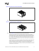
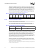
Although the CEK heatsink fits into the legacy volumetric keep-in, it has a larger footprint due to
the elimination of retention mechanism and clips used in the older enabled thermal/mechanical
components. This allows the heatsink to grow its base and fin dimensions, further improving the
thermal performance. A drawback of this enlarged size and use of copper for both the base and fins
is the increased weight of the heatsink. The CEK heatsink is estimated to weigh twice as much as
previous heatsinks used with Intel Xeon Processors. However, the new retention scheme
employed by CEK is designed to support heavy heatsinks (approximately up to 1000 grams) in
cases of shock, vibration and installation as explained in Appendix A. Some of the thermal and
mechanical characteristics of the CEK heatsinks are shown in Table 2-15.
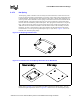
2.4.7.2 Thermal Interface Material (TIM-2)
A TIM must be applied between the package and the heatsink to ensure thermal conduction. The
CEK reference design uses Shin-Etsu* G751 thermal grease.
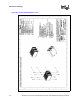
The recommended grease dispenses weight to ensure full coverage of the processor IHS is given
below. For an alternate TIM, full coverage of the entire processor IHS is recommended.
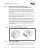
It is recommended that you use thermally conductive grease as the TIM requires special handling
and dispense guidelines. The following guidelines apply to Shin-Etsu G751 thermal grease. The
use of a semi-automatic dispensing system is recommended for high volume assembly to ensure an
accurate amount of grease is dispensed on top of the IHS prior to assembly of the heatsink. A
typical dispense system consists of an air pressure and timing controller, a hand held output
dispenser, and an actuation foot switch. Thermal grease in cartridge form is required for dispense
system compatibility. A precision scale with an accuracy of ±5 mg is recommended to measure the
correct dispense weight and set the corresponding air pressure and duration. The IHS surface
should be free of foreign materials prior to grease dispense
Additional recommendations include recalibrating the dispense controller settings after any two
hour pause in grease dispense. The grease should be dispensed just prior to heatsink assembly to
prevent any degradation in material performance. Finally, the thermal grease should be verified to
be within its recommended shelf life before use.
The CEK reference solution is designed to apply a compressive load of up to N [ lbf] on the TIM
to improve the thermal performance.
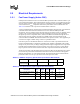
Table 2-15. CEK Heatsink Thermal Mechanical Characteristics
Size
Height (cm)
[in.]
Weight
(kg) [lbs]
Target Airflow
Through Fins
(CFM)
Mean Ψ
ca
(°C/W)
Standard
Deviation Ψ
ca
(°C/W)
Pressure Drop
(in H
2
O)
2U+ 5.08 [2.00] 1.0 [2.2] 22 0.280.245 0.0086 0.17
1U 2.64 [1.04] 680 [1.5] 15 0.352 0.0106 0.24
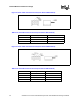
Table 2-16. Recommended Thermal Grease Dispense Weight
Processor
Recommended
Thermal Grease
Dispense Weight
(mg)
Intel Xeon Processor
with 800 MHz System
Bus
Shin-Etsu* G751 400