
Intel Xeon Processor with 800 MHz System Bus Thermal/Mechanical Design Guide

Intel® Xeon™ Processor with 800 MHz System Bus Thermal/Mechanical Design Guidelines 29
Thermal/Mechanical Reference Design
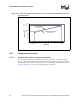
Figure 2-13 below shows the comparison of this reference thermal solution’s Thermal Profile to the
Intel Xeon Processor with 800 MHz System Bus Thermal Profile A specification. The 2U+ CEK
solution meets the Thermal Profile A with a 2.5 °C margin at the lower end (Pcontrol_base_A) and
a 0.4 °C margin at the upper end (TDP). By designing to Thermal Profile A, it is ensured that no
measurable performance loss due to TCC activation is observed under the given environmental
conditions.
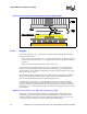
The 1U CEK Intel reference thermal solution is designed to meet the Thermal Profile B for the
Intel Xeon Processor with 800 MHz System Bus. From Tab le 2- 6 the three-sigma (mean+3sigma)
performance of the thermal solution is computed to be 0. °C/W and the processor local ambient
temperature (T
LA
) for this thermal solution is 40 °C. Hence, the Thermal Profile equation for this
thermal solution is calculated as:
Equation 14.
where,
y = Processor T
CASE
value (°C)
x = Processor power value (W)
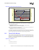
Figure 2-9 below shows the comparison of this reference thermal solution’s Thermal Profile to the
Intel Xeon Processor with 800 MHz System Bus Thermal Profile B specification. The 1U CEK
solution meets the Thermal Profile B with a 3.4 °C margin at the lower end (Pcontrol_base_B) and
a 0.5°C margin at the upper end (TDP). However, as explained in Chapter 2.2.3, designing to
Thermal Profile B results in increased TCC activation and measurable performance loss for the
processor. In this case, it is estimated that up to 5% of all the processors in a population that
utilizes the 1U CEK reference solution may see TCC activation that results in a measurable
performance loss of >1.5% when running an application that consumes power equivalent to TDP.