
Intel Xeon Processor and Intel E7500/E7501Chipset Compatible Platform Design Guide


I/O Controller Hub 3 (Intel
®
ICH3-S)
148 Intel
®
Xeon™ Processor and Intel
®
E7500/E7501 Chipset Compatible Platform Design Guide
9.4.2 USB Routing Parameters
Use the following separation guidelines.
• Recommended trace width and separation is 5-mil trace width with 6-mil spacing
(90
Ω differential impedance).
• Maintain parallelism between USB differential signals, with the trace spacing needed to
achieve 90
Ω differential impedance.
• Use at a minimum 20-mil spacing between USB signal pair and other traces on the PCB. This
helps to prevent crosstalk. If possible, keep clock and PCI traces at least 50 mils from the USB
differential pairs.
• Minimize the length of high-speed clock and periodic signal traces that run parallel to USB
signal lines to minimize crosstalk.
• Trace length match USB signal pair traces. The maximum trace length mismatch between
USB signal pair should be no greater than 150 mils.
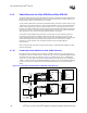
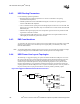
9.4.3 EMI Considerations
An optional 47 pF capacitor may be placed as close to the USB connector as possible on the USB
data lines. This capacitor can be used for improved signal quality (rise/fall time), and to help
minimize EMI radiation.
Note: Any EMI or ESD solution should be placed as close to the port as possible. For example, if using a
front-panel daughtercard, the EMI/ESD solution should be placed on the daughtercard.
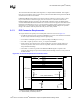
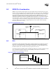
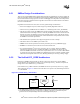
9.4.4 USB Power Line Layout Topologies
The following is a suggested topology for power distribution of VBUS to USB ports. Circuits of
this type provide two types of protection during dynamic attach and detach situations on the bus:
inrush current limiting (droop), and dynamic detach flyback protection. These two different
situations require both bulk capacitance (droop) and filtering capacitance (for dynamic detach
flyback voltage filtering). It is important to minimize the inductance and resistance between the
coupling capacitors and the USB ports. That is, capacitors should be placed as close as possible to
the port, and the power-carrying traces should be as wide as possible, preferably a plane.
Figure 9-5. Suggested USB Downstream Power Connection
Port1
Port2
G
G
n
n
d
d
V
V
c
c
c
c
4
4
1
1
47 pF
Thermistor
220 uF
G
G
n
n
d
d
V
V
c
c
c
c
4
4
1
1
47 pF
5V
5V
Switch
5V Sus