
64-bit Intel Xeon Processorwith 1MB L2 Cache Thermal/Mechanical Design Guidelines
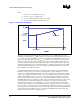
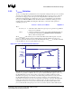
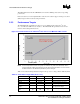
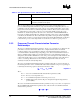
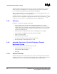
Table Of Contents
R
Thermal/Mechanical Reference Design
64-bit Intel
®
Xeon™ Processor MP with 1 MB L2 Cache 15
Thermal/Mechanical Design Guidelines
Table 2-2. Performance Target Table (Sheet 2 of 2)
Parameter Minimum Maximum Unit Notes
T
CASE_MAX
73 °C In case of conflict, datasheet
supercedes TMDG.
T
CASE_MAX
@
Pcontrol_base
50 °C Pcontrol_base = 20 W
T
LA
40 °C
TDP 110 W In case of conflict, datasheet
supercedes TMDG.
2.3 Characterizing Cooling Solution Performance
Requirements
2.3.1 Fan Speed Control
Fan speed control (FSC) techniques to reduce system level acoustic noise are a common practice in
server designs. The fan speed is one of the parameters that determine the amount of airflow
provided to the thermal solution. Additionally, airflow is proportional to a thermal solution’s
performance, which consequently determines the T
CASE
of the processor at a given power level.
Since the T
CASE
of a processor is an important parameter in the long-term reliability of a processor,
the FSC implemented in a system directly correlates to the processor’s ability to meet the Thermal
Profile and hence the long-term reliability requirements. For this purpose, the parameter called
T
CONTROL
as explained in Section 2.2.2, is to be used in FSC designs to ensure that the long-term
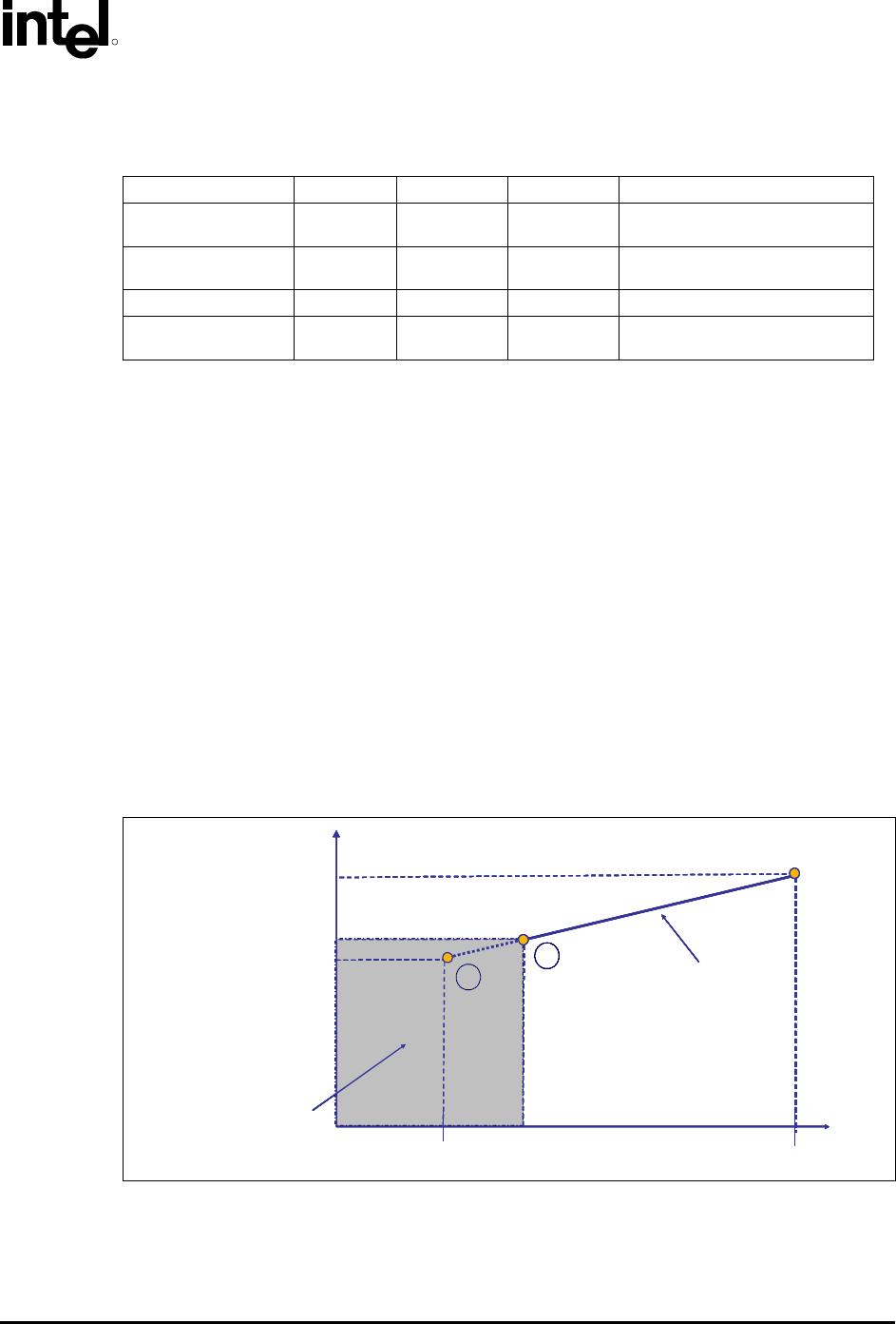
reliability of the processor is met while keeping the system level acoustic noise down. Figure 2-6
depicts the relationship between T
CONTROL
and FSC methodology.
Figure 2-6. T
CONTROL
and Fan Speed Control
Pcontrol_base
TDP
T
CASE
T
CASE
MAX
T
CASE
@
Pcontrol_base
Power
Thermal Profile
T
CASE
@ T
CONTROL
Pcontrol
2
Fan speed control region
1
Pcontrol_base
TDP
T
CASE
T
CASE
MAX
T
CASE
@
Pcontrol_base
Power
Thermal Profile
T
CASE
@ T
CONTROL
Pcontrol
2
Fan speed control region
1
T
CASE
MAX
T
CASE
MAX@T
CONTROL
T
CASE
MAX@
Pcontrol_base
Pcontrol_base
TDP
T
CASE
T
CASE
MAX
T
CASE
@
Pcontrol_base
Power
Thermal Profile
T
CASE
@ T
CONTROL
Pcontrol
2
Fan speed control region
1
Pcontrol_base
TDP
T
CASE
T
CASE
MAX
T
CASE
@
Pcontrol_base
Power
Thermal Profile
T
CASE
@ T
CONTROL
Pcontrol
2
Fan speed control region
1
T
CASE
MAX
T
CASE
MAX@T
CONTROL
T
CASE
MAX@
Pcontrol_base
Once the T
CONTROL
value is determined as explained earlier, the thermal diode temperature reading
from the processor can be compared to this T
CONTROL
value. A fan speed control scheme can be
implemented as described in Table 2-3 without compromising the long-term reliability of the
processor.