
64-bit Intel Xeon Processor with 2MB L2 Cache Thermal/Mechanical Design Guidelines

64-bit Intel® Xeon™ Processor with 2MB L2 Cache Thermal/Mechanical Design Guidelines 35
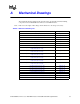
Thermal/Mechanical Reference Design
products is called the Common Enabling Kit, or CEK. The CEK base is compatible with all
three heatsink solutions.
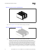
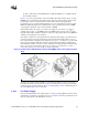
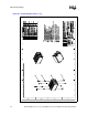
Figure 2-17 provides a representation of the active CEK solution. This design is based on a 4-pin
PWM/T-diode controlled active fan heatsink solution. This new solution is being offered to help
provide better control over pedestal chassis acoustics. This is achieved though accurate
measurement of processor temperature through the processor’s temperature diode (T-diode). Fan
RPM is modulated through the use an ASIC located on the serverboard, that sends out a PWM
control signal to the 4th pin of the connector labeled as Control.
This heatsink solution also requires a constant +12 V supplied to pin 2 and does not support
variable voltage control or 3-pin PWM control. If no PWM signal is detected on the 4
th
pin this
heatsink solution will revert back to thermistor control mode, supporting both the 4-wire PWM and
standard 3-wire ambient air control methods.
The solution is still under development at this time. Intel may make changes to specification and
product descriptions at any time, without notice. The active heatsink solution will not exceed a
mass of approximately 1150 grams. Note that this is per processor, so a dual processor system will
have up to approximately 2300 grams total mass in the heatsinks. This large mass will require a
minimum chassis stiffness to be met in order to withstand force during shock and vibration. Please
refer to Chassis Strength and Stiffness Measurement and Improvement Guidelines, for Direct
Chassis Attach Solutions for more details on chassis requirements.
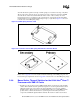
Clearance is required around the heatsink to ensure unimpeded airflow for proper cooling. The
physical baseboard keepout requirements for the active solution are the same as the passive CEK
solution shown in Appendix A. Refer to Figure A-18 through Figure A-20 for additional details on
the active CEK thermal solution volumetrics.
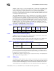
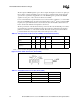
2.4.8.1 Fan Power Supply
The active heatsink includes a fan, which requires a +12 V power supply. Platforms must provide a
matched fan power header to support the boxed processor. Table 2-6 contains specifications for the
input and output signals at the heatsink fan connector.
Figure 2-17. Boxed Active CEK Heatsink Solutions with PWM/T-diode control (Representation
Only)