
603 Pin Socket Design Guidelines


603 Pin Socket Design Guidelines
R
25
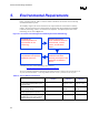
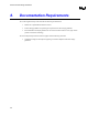
Use Environment Speculative Stress
Condition
7 year life
expectation
10 year life
expectation
Shipping & Handling Mechanical Shock
50g trapezoidal profile;
170”/sec Velocity change; 11
msec duration pulse
3 drops / axis 6
axis
Shipping & Handling Random Vibration
3.13 gRMS, random,
5 Hz - 20 Hz .01 g2/Hz sloping
up to .02 g2/Hz 20 Hz - 500 Hz
.02 g2/Hz
10 min / axis, 3
axis
5.1. Porosity Test
5.1.1. Porosity Test Method:
Use EIA 364, Test Procedure 53A, Nitric acid test. Porosity test to be performed for 20 contacts,
randomly selected per socket, 5 sockets.
5.1.2. Porosity Test Criteria:
Maximum of two pores per set of 20 contacts, as measured per EIA 364, Test Procedure 60.
5.2. Plating Thickness
Measure various plating thickness on contact surface per EIA 364, Test Procedure 48, Method C or
Method A. Test to be performed using 20 randomly selected contacts per socket, 5 sockets. No plating
thickness measured shall be less than the minimum plating thickness specified in Sections 3.3.4.3.
5.3. Solvent Resistance
Requirement: No damage to ink markings if applicable. EIA 364-11A
5.4. Solderability
(Applicable for leaded sockets) Requirement: 95% coverage per ball/surface mount feature.
EIA 364, Test Procedure 52, Class 2, Category 3. Test to be performed on 20 randomly selected
contacts per socket, 5 sockets.
5.5. Durability
Use per EIA 364, test procedure 09B. Same package pin field to be used for 1st and 51st cycles.
Measure contact resistance when mated in 1st and 51st cycles. A spare package pin field is used for 2nd
through 50th cycles. A pair of new package pin fields to be used for each of the socket samples. The
package should be removed at the end of each de-actuation cycle and reinserted into the socket.