
Intel 64 and IA-32 Architectures Software Developers Manual Volume 2B, Instruction Set Reference, N-Z

A-6 Vol. 2B
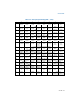
OPCODE MAP
Example A-2. Look-up Example for 2-Byte Opcodes
Look-up opcode 0FA4050000000003H for a SHLD instruction using Table A-3.
• The opcode is located in row A, column 4. The location indicates a SHLD
instruction with operands Ev, Gv, and Ib. Interpret the operands as follows:
— Ev: The ModR/M byte follows the opcode to specify a word or doubleword
operand.
— Gv: The reg field of the ModR/M byte selects a general-purpose register.
— Ib: Immediate data is encoded in the subsequent byte of the instruction.
• The third byte is the ModR/M byte (05H). The mod and opcode/reg fields of
ModR/M indicate that a 32-bit displacement is used to locate the first operand in
memory and eAX as the second operand.
• The next part of the opcode is the 32-bit displacement for the destination
memory operand (00000000H). The last byte stores immediate byte that
provides the count of the shift (03H).
• By this breakdown, it has been shown that this opcode represents the
instruction: SHLD DS:00000000H, EAX, 3.
A.2.4.3 Three-Byte Opcode Instructions
The three-byte opcode maps shown in Table A-4 and Table A-5 includes primary
opcodes that are either 3 or 4 bytes in length. Primary opcodes that are 3 bytes in
length begin with two escape bytes 0F38H or 0F3A. The upper and lower four bits of
the third opcode byte are used to index a particular row and column in Table A-4 or
Table A-5.
Three-byte opcodes that are 4 bytes in length begin with a mandatory prefix (66H,
F2H, or F3H) and two escape bytes (0F38H or 0F3AH). The upper and lower four bits
of the fourth byte are used to index a particular row and column in Table A-4 or Table
A-5.
For each entry in the opcode map, the rules for interpreting the byte following the
primary opcode fall into the following case:
• A ModR/M byte is required and is interpreted according to the abbreviations listed
in Section A.1 and Chapter 2, “Instruction Format,” of the Intel® 64 and IA-32
Architectures Software Developer’s Manual, Volume 2A. The operand types are
listed according to notations listed in Section A.2.
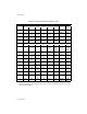
Example A-3. Look-up Example for 3-Byte Opcodes
Look-up opcode 660F3A0FC108H for a PALIGNR instruction using Table A-5.
• 66H is a prefix and 0F3AH indicate to use Table A-5. The opcode is located in row
0, column F indicating a PALIGNR instruction with operands Vdq, Wdq, and Ib.
Interpret the operands as follows:
— Vdq: The reg field of the ModR/M byte selects a 128-bit XMM register.