Mobile Intel Pentium 4 Processor with 533 MHz Front Side Bus Datasheet January 2004 Order Number: 253028-004
Information in this document is provided solely to enable use of Intel products. Intel assumes no liability whatsoever, including infringement of any patent or copyright, for sale and use of Intel products except as provided in Intel's Terms and Conditions of Sale for such products. Information contained herein supersedes previously published specifications on these devices from Intel.
Contents Contents 1 Introduction...................................................................................................................................... 9 1.1 1.2 1.3 2 Electrical Specifications ................................................................................................................. 13 2.1 2.2 2.3 2.4 2.5 2.6 2.7 2.8 2.9 2.10 2.11 2.12 2.13 3 Package Load Specifications..............................................................................................
Contents 5.2.3 5.2.4 5.2.5 6 Configuration and Low Power Features ........................................................................................ 71 6.1 6.2 6.3 7 Power-On Configuration Options........................................................................................ 71 Clock Control and Low Power States ................................................................................. 71 6.2.1 Normal State............................................................................
Contents Figures 1 2 3 4 5 6 7 8 9 10 11 12 13 14 15 16 VCCVID Pin Voltage and Current Requirements ....................................................................... 15 Phase Lock Loop (PLL) Filter Requirements............................................................................. 17 Vcc Static and Transient Tolerance............................................................................................26 ITPCLKOUT[1:0] Output Buffer Diagram................................................
Contents Tables 1 2 3 4 5 6 7 8 9 10 11 12 13 14 15 16 17 18 19 20 21 22 23 24 25 26 27 6 References ................................................................................................................................. 12 VCCVID Pin Voltage Requirements ........................................................................................... 14 Voltage Identification Definition ..................................................................................................
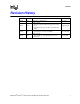
Contents Revision History Document ID Revision 253028 001 Description Initial release of the Datasheet Date June 2003 Updates include: 253028 • Added Intel HyperThreading Technology and 3.
Contents This page intentionally left blank.
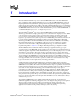
Introduction 1 Introduction The mobile Intel Pentium 4 processor with 533 MHz FSB is based on the Intel NetBurstTM micro-architecture. The mobile Intel Pentium 4 processor with 533-MHz FSB utilizes a 478-pin Flip-Chip Pin Grid Array (FC-PGA2) package with an integrated heat spreader, and plugs into a surface-mount, Zero Insertion Force (ZIF) socket. The mobile Intel Pentium 4 processor maintains full compatibility with IA-32 software.
Introduction The processor’s 533 MHz Intel NetBurst micro-architecture FSB utilizes a split-transaction, deferred reply protocol like the Intel Pentium 4 processor. This FSB is not compatible with the P6 processor family bus. The 533-MHz Intel NetBurst micro-architecture FSB uses SourceSynchronous Transfer (SST) of address and data to improve performance by transferring data four times per bus clock (4X data transfer rate, as in AGP 4X).
Introduction • FC-PGA2 package — Flip-Chip Pin Grid Array package with 50-mil pin pitch and Integrated Heat Spreader • Integrated heat spreader — The surface used to make contact between a heatsink or other thermal solution and the processor. Abbreviated IHS.
Introduction 1.2 References Material and concepts available in the following documents may be beneficial when reading this document. Table 1. References Document Intel 852GM/852PM Chipset Platforms Design Guide Intel Mobile Processor Micro-FCPGA Package and Socket Manufacturing and Mechanical User’s Guide Intel 852GM Chipset Datasheet Intel Architecture Software Developer's Manual Mobile Intel Pentium 4 Processor with 533 MHz FSB Specification Update Order Number http://developer.intel.
Electrical Specifications 2 Electrical Specifications 2.1 FSB and GTLREF Most mobile Intel Pentium 4 processor FSB signals use Gunning Transceiver Logic (GTL+) signalling technology. As with the Intel P6 family of microprocessors, this signalling technology provides improved noise margins and reduced ringing through low-voltage swings and controlled edge rates.
Electrical Specifications 2.3.1 VCC Decoupling Regulator solutions need to provide bulk capacitance with a low Effective Series Resistance (ESR) and keep a low interconnect resistance from the regulator to the socket. Bulk decoupling for the large current swings when the part is powering on, or entering/exiting low-power states, must be provided by the voltage regulator solution. For more details on decoupling recommendations, please refer to the appropriate platform design guidelines listed in Table 1.
Electrical Specifications Figure 1. VCCVID Pin Voltage and Current Requirements 1.2V+10% 1.2V-5% 1.0V VCCVID VIDs latched 30mA 1mA 4ns Table 3. Voltage Identification Definition (Sheet 1 of 2) Processor Pins VID4 VID3 VID2 VID1 VID0 1 1 1 1 1 VRM output off 1 1 1 1 0 1.100 1 1 1 0 1 1.125 1 1 1 0 0 1.150 1 1 0 1 1 1.175 1 1 0 1 0 1.200 1 1 0 0 1 1.225 1 1 0 0 0 1.250 1 0 1 1 1 1.275 1 0 1 1 0 1.300 1 0 1 0 1 1.
Electrical Specifications Table 3. 2.4.1 Voltage Identification Definition (Sheet 2 of 2) 0 1 0 1 0 1.600 0 1 0 0 1 1.625 0 1 0 0 0 1.650 Enhanced Intel SpeedStep®Technology The mobile Intel Pentium 4 processor, when used in conjunction with the requisite Intel SpeedStep® technology applet or its equivalent, supports Enhanced Intel SpeedStep technology.
Electrical Specifications . Figure 2. Phase Lock Loop (PLL) Filter Requirements 0.2 dB 0 dB -0.5 dB forbidden zone -28 dB forbidden zone -34 dB DC 1 Hz fpeak 1 MHz passband 66 MHz fcore high frequency band NOTES: 1. Diagram not to scale. 2. No specification for frequencies beyond fcore (core frequency). 3. fpeak, if existent, should be less than 0.05 MHz. 2.4.
Electrical Specifications 2.5 Signal Terminations, Unused Pins, and TESTHI[10:0] All NC pins must remain unconnected. Connection of these pins to VCC, VSS, or to any other signal (including each other) can result in component malfunction or incompatibility with future mobile Intel Pentium 4 processors. See Section 5.2 for a pin listing of the processor and the location of all NC pins.
Electrical Specifications As an alternative, group 2 (TESTHI[5:2]), and the ITPCLKOUT[1:0] pins may be tied directly to the processor VCC. This has no impact on system functionality. TESTHI[0] may also be tied directly to processor VCC if resistor termination is a problem, but matched resistor termination is recommended. In the case of the ITPCLKOUT[1:0] pins, direct tie to VCC is strongly discouraged for system boards that do not implement an onboard debug port.
Electrical Specifications Table 4.
Electrical Specifications 2.7 Asynchronous GTL+ Signals Mobile Intel Pentium 4 processor does not utilize CMOS voltage levels on any signals that connect to the processor. As a result, legacy input signals such as A20M#, IGNNE#, INIT#, LINT0/INTR, LINT1/NMI, SMI#, SLP#, and STPCLK# use GTL+ input buffers. Legacy output FERR#/PBE# and other non-GTL+ signals (THERMTRIP#) utilize GTL+ output buffers. PROCHOT# uses GTL+ input/output buffer.
Electrical Specifications 2.10 Maximum Ratings Table 6 lists the processor’s maximum environmental stress ratings. The processor should not receive a clock while subjected to these conditions. Functional operating parameters are listed in the AC and DC tables. Extended exposure to the maximum ratings may affect device reliability.
Electrical Specifications Table 7. Voltage and Current Specifications Symbol Parameter Min Max Unit V Refer to Table 9 and Figure 3 Vcc for Processor at VID=1.200 V: 1.60 GHz Typ 1.070 1.140 1.300 1.295 1.290 1.265 1.260 1.380 1.370 1.370 1.345 1.350 1.325 1.320 1.315 1.290 1.285 1.405 1.395 1.395 1.370 1.370 1.355 1.345 1.340 1.315 1.310 1.430 1.420 1.420 1.395 1.395 1.340 1.335 1.425 1.420 Notes 2,3,4,5,10 Vcc for Processor at VID=1.475 V: 2.40 GHz 2.66 GHz 2.80 GHz 3.06 GHz 3.
Electrical Specifications NOTES: 1. Unless otherwise noted, all specifications in this table are based on the latest silicon measurements available at time of publication. Listed frequency and VID combinations are not necessarily committed production frequency and VID combinations. 2. These voltages are targets only. A variable voltage source should exist on systems in the event that a different voltage is required. See Section 2.4 and Table 3 for more information.
Electrical Specifications Table 8. Vcc Static and Transient Tolerance Voltage Deviation from VID Setting (V)1,2,3 Icc (A) Maximum Typical Minimum 0 0.000 -0.025 -0.050 5 -0.010 -0.036 -0.062 10 -0.019 -0.047 -0.075 15 -0.029 -0.058 -0.087 20 -0.038 -0.069 -0.099 25 -0.048 -0.079 -0.111 30 -0.057 -0.090 -0.124 35 -0.067 -0.101 -0.136 40 -0.076 -0.112 -0.148 45 -0.085 -0.123 -0.160 50 -0.095 -0.134 -0.173 55 -0.105 -0.145 -0.185 60 -0.114 -0.156 -0.
Electrical Specifications Figure 3. Vcc Static and Transient Tolerance VID+50mV VID Vcc Maximum Vcc [V] VID-50mV VID-100mV Vcc Typical VID-150mV Vcc Minimum VID-200mV VID-250mV 0 10 20 30 40 50 60 70 Icc [A] NOTES: 1. The loadline specification includes both static and transient limits. 2. Refer to Table 8 for specific offsets from VID voltage which apply to all VID settings. 3. The loadlines specify voltage limits at the die measured at VCC_sense and Vss_sense pins.
Electrical Specifications Table 9. FSB Differential BCLK Specifications Notes1 Symbol Parameter Min Typ Max Unit Figure VL Input Low Voltage -0.150 0.000 N/A V 8 VH Input High Voltage 0.660 0.700 0.850 V 8 VCROSS(abs) Absolute Crossing Point 0.250 N/A 0.550 V 8, 9 2,3,8 VCROSS(rel) Relative Crossing Point V 8, 9 2,3,8,9 ∆VCROSS Range of Crossing Points N/A N/A 0.140 V 8, 9 2,10 VOV Overshoot N/A N/A VH + 0.3 V 8 4 VUS Undershoot -0.
Electrical Specifications Table 10. GTL+ Signal Group DC Specifications Symbol Parameter Min Max Unit Notes1 GTLREF Reference Voltage 2/3 Vcc - 2% 2/3 Vcc + 2% V 10 GTLREF_COMPATIBLE Reference Voltage 0.63*Vcc - 2% 0.63*Vcc + 2% V 10 VIH Input High Voltage 1.10*GTLREF VCC V 2,6 VIL Input Low Voltage 0.0 0.
Electrical Specifications Table 11. Asynchronous GTL+ Signal Group DC Specifications Symbol VIH VIL Unit Notes1 V 3, 4, 5 0.9*GTLREF V 5 Parameter Min Max Input High Voltage 1.10*GTLREF VCC 0 Asynch GTL+ Input Low Voltage Asynch. GTL+ VOH Output High Voltage N/A VCC V 2, 3, 4 IOL Output Low Current N/A 50 mA 6, 8 IHI Pin Leakage High N/A 100 µA 9 ILO Pin Leakage Low N/A 500 µA 10 7 11 Ω 5, 7 8.4 13.
Electrical Specifications Table 12.
Electrical Specifications Figure 4. ITPCLKOUT[1:0] Output Buffer Diagram Vcc Ron To Debug Port Processor Package Rext NOTES: 1. See Table 13 for range of Ron. 2. The Vcc referred to in this figure is the instantaneous Vcc. 3. Refer to the ITP700 Debug Port Design Guide and the appropriate platform design guidelines for the value of Rext. Table 14. BSEL [1:0] and VID[4:0] DC Specifications Symbol Parameter Min Max Unit Notes1 Ron (BSEL) Buffer On Resistance 9.2 14.
Electrical Specifications Table 15. VCC Overshoot Specifications Symbol Parameter VOS_MAX TOS_MAX Min Typ Max Unit Figure Magnitude of VCC overshoot above VID 0.050 V 5 Time duration of VCC overshoot above VID 25 µs 5 Notes Figure 5. VCC Overshoot Example Waveform Example Overshoot Waveform Voltage (V) VID + 0.050 VOS VID - 0.000 TOS 0 5 10 15 20 Time (ns) TOS: Overshoot time above VID VOS: Overshoot above VID NOTES: 1. Vos is measured overshoot voltage. 2.
Electrical Specifications 2.13 GTL+ FSB Specifications Routing topology recommendations may be found in the appropriate platform design guidelines listed in Table 1. Termination resistors are not required for most GTL+ signals, as these are integrated into the processor silicon. Valid high and low levels are determined by the input buffers which compare a signal’s voltage with a reference voltage called GTLREF (known as VREF in previous documentation). Table 16 lists the GTLREF specifications.
Electrical Specifications Figure 6. Test Circuit VCC VCC Rload= 50 ohms 420 mils, 50 ohms, 169 ps/in 2.4nH 1.
Package Mechanical Specifications 3 Package Mechanical Specifications The mobile Intel Pentium 4 processor with 533 MHz FSB is packaged in a 478-pin, FC-PGA2 package. Components of the package include an integrated heat spreader (IHS), processor die, and the substrate which is the pin carrier. Different views of the package are shown in Figure 7 through Figure 12. Package dimensions are shown in Table 17. Note: For Figure 7 through Figure 12, the following notes apply: 1.
Package Mechanical Specifications Figure 8.
Package Mechanical Specifications Table 17. Description Table for Processor Dimensions Dimension (mm) Code Letter Notes Min Nominal Max A1 2.266 2.378 2.490 Original Package (6 layer) A2 0.980 1.080 1.180 Original Package (6 layer) A1 2.42 2.55 2.67 Equivalent Package (8 layer) A2 1.13 1.20 1.27 Equivalent Package (8 layer) B1 30.800 31.000 31.200 B2 30.800 31.000 31.200 C1 33.000 Includes Placement Tolerance C2 33.000 Includes Placement Tolerance D 34.900 35.
Package Mechanical Specifications Figure 10. Processor Pin Detail Ø 0.305±0.025 Ø 0.65 MAX PINHEAD DIAMETER Ø 1.032 MAX KEEP OUT ZONE 0.3 MAX SOLDER FILLET HEIGHT 2.03±0.08 ALL DIMENSIONS ARE IN MILIMETERS NOTES: 1. Pin plating consists of 0.2 micrometers Au over 2.0 micrometer Ni. 2. 0.254 mm diametric true position, pin to pin. Figure 11. IHS Flatness Specification IHS SUBSTRATE NOTES: 1. Flatness is specific as overall, not per unit of length. 2. All dimensions are in millimeters.
Package Mechanical Specifications Figure 12. FC-PGA2 Package - Bottom View 14 (K3) AF AD AB Y V T P M K H F D B AE AC AA W U R 14 (K3) N L J G E C A 1 25X 1.27 (e) 3 2 5 4 7 6 9 8 10 11 13 15 17 19 21 23 25 12 14 16 18 20 22 24 26 25X 1.27 (e) NOTE: All dimensions in millimeters. Values shown are for reference only. The mobile Intel Pentium 4 processor with 533 MHz FSB may contain pin side capacitors mounted to the processor package.
Package Mechanical Specifications 3.1 Package Load Specifications Table 18 provides dynamic and static load specifications for the processor IHS. These mechanical load limits should not be exceeded during heatsink assembly, mechanical stress testing, or standard drop and shipping conditions. The heatsink attach solutions must not induce continuous stress onto the processor with the exception of a uniform load to maintain the heat sink-to-processor thermal interface contact.
Package Mechanical Specifications 3.4 Processor Materials The mobile Intel Pentium 4 processor with 533 MHz FSB is assembled from several components. The basic material properties are described in Table 22. Table 20. Processor Material Properties Component Material Integrated Heat Spreader Nickel over copper Substrate Fiber-reinforced resin Substrate pins 3.
Package Mechanical Specifications Figure 14. The Coordinates of the Processor Pins as Viewed From the Top of the Package.
Pin Listing and Signal Definitions 4 Pin Listing and Signal Definitions 4.1 Mobile Intel Pentium 4 Processor Pin Assignments Section 4.1 contains the preliminary pin list for the mobile Intel Pentium 4 processor with 533 MHz FSB in Table 21 and Table 22. Table 21 is a listing of all processor pins ordered alphabetically by pin name. Table 22 is also a listing of all processor pins but ordered by pin number.
Pin Listing and Signal Definitions Table 21. Table 21.
Pin Listing and Signal Definitions Table 21. Pin Name Pin Listing by Pin Name Pin Number Signal Buffer Type Table 21.
Pin Listing and Signal Definitions Table 21. Pin Name Pin Listing by Pin Name Pin Number Signal Buffer Type Table 21.
Pin Listing and Signal Definitions Table 21. Pin Name Pin Listing by Pin Name Pin Number Signal Buffer Type Table 21.
Pin Listing and Signal Definitions Table 21. Pin Name Pin Listing by Pin Name Pin Number Signal Buffer Type Table 21.
Pin Listing and Signal Definitions Table 21. Pin Name Pin Listing by Pin Name Pin Number Signal Buffer Type Table 21.
Pin Listing and Signal Definitions Table 21. Pin Listing by Pin Name Pin Number Pin Name Signal Buffer Type Table 22.
Pin Listing and Signal Definitions Table 22. Pin Listing by Pin Number Pin Number Pin Name Signal Buffer Type Direction Table 22.
Pin Listing and Signal Definitions Table 22. Pin Listing by Pin Number Pin Number Pin Name Signal Buffer Type Direction Table 22.
Pin Listing and Signal Definitions Table 22. Pin Listing by Pin Number Pin Number Pin Name Signal Buffer Type Direction Table 22.
Pin Listing and Signal Definitions Table 22. Pin Listing by Pin Number Pin Number Pin Name Signal Buffer Type Direction Table 22.
Pin Listing and Signal Definitions Table 22. Pin Listing by Pin Number Pin Number Pin Name Signal Buffer Type Direction Table 22.
Pin Listing and Signal Definitions Table 22.
Pin Listing and Signal Definitions 4.2 Alphabetical Signals Reference Table 23. Signal Description (Sheet 1 of 8) Name Type Description 36 A[35:3]# Input/ Output A[35:3]# (Address) define a 2 -byte physical memory address space. In subphase 1 of the address phase, these pins transmit the address of a transaction. In sub-phase 2, these pins transmit transaction type information. These signals must connect the appropriate pins of all agents on the Mobile Intel Pentium 4 Processor FSB.
Pin Listing and Signal Definitions Table 23. Signal Description (Sheet 2 of 8) Name Type Description BINIT# (Bus Initialization) may be observed and driven by all processor FSB agents and if used, must connect the appropriate pins of all such agents. If the BINIT# driver is enabled during power-on configuration, BINIT# is asserted to signal any bus condition that prevents reliable future operation.
Pin Listing and Signal Definitions Table 23. Signal Description (Sheet 3 of 8) Name Type Description D[63:0]# (Data) are the data signals. These signals provide a 64-bit data path between the processor FSB agents, and must connect the appropriate pins on all such agents. The data driver asserts DRDY# to indicate a valid data transfer. D[63:0]# are quad-pumped signals and will thus be driven four times in a common clock period. D[63:0]# are latched off the falling edge of both DSTBP[3:0]# and DSTBN[3:0]#.
Pin Listing and Signal Definitions Table 23. Signal Description (Sheet 4 of 8) Name Type Description DPSLP# Input DPSLP# when asserted on the platform causes the processor to transition from the Sleep State to the Deep Sleep state. In order to return to the Sleep State, DPSLP# must be deasserted and BCLK[1:0] must be running. DRDY# Input/ Output DRDY# (Data Ready) is asserted by the data driver on each data transfer, indicating valid data on the data bus.
Pin Listing and Signal Definitions Table 23. Signal Description (Sheet 5 of 8) Name HIT# HITM# IERR# Type Input/ Output Input/ Output Output Description HIT# (Snoop Hit) and HITM# (Hit Modified) convey transaction snoop operation results. Any FSB agent may assert both HIT# and HITM# together to indicate that it requires a snoop stall, which can be continued by reasserting HIT# and HITM# together. IERR# (Internal Error) is asserted by a processor as the result of an internal error.
Pin Listing and Signal Definitions Table 23. Signal Description (Sheet 6 of 8) Name LOCK# Type Input/ Output Description LOCK# indicates to the system that a transaction must occur atomically. This signal must connect the appropriate pins of all processor FSB agents. For a locked sequence of transactions, LOCK# is asserted from the beginning of the first transaction to the end of the last transaction.
Pin Listing and Signal Definitions Table 23. Signal Description (Sheet 7 of 8) Name RS[2:0]# RSP# SKTOCC# SLP# SMI# Type Input Input Output Input Input Description RS[2:0]# (Response Status) are driven by the response agent (the agent responsible for completion of the current transaction), and must connect the appropriate pins of all processor FSB agents.
Pin Listing and Signal Definitions Table 23. Signal Description (Sheet 8 of 8) Name THERMTRIP# Description Output Assertion of THERMTRIP# (Thermal Trip) indicates the processor junction temperature has reached a level beyond which permanent silicon damage may occur. Measurement of the temperature is accomplished through an internal thermal sensor which is configured to trip at approximately 135°C.
Thermal Specifications and Design Considerations 5 Thermal Specifications and Design Considerations 5.1 Processor Thermal Specifications The mobile Intel Pentium 4 processor with 533 MHz FSB processor requires a thermal solution to maintain temperatures within the operating limits as set forth in Section 5.1.1. Any attempt to operate the processor outside these operating limits may result in permanent damage to the processor and potentially other components within the system.
Thermal Specifications and Design Considerations Table 24. Processor Thermal Design Power Thermal Design Power 1,2 (W) Minimum TCASE (°C) Maximum TCASE (°C) 2.40 GHz 59.8 5 71 2.66 GHz 66.1 5 74 5 2.80 GHz 68.4 5 75 5 3.06 GHz 70 5 74 5 3.20 GHz 76 5 72 FMS0 70 5 74 5 4 FMS0.5 76 5 72 4 Processor and Core Frequency 3 Notes Processors with multiple VIDs: NOTES: 1. These values are specified at VCC_MAX for the processor.
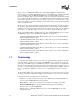
Thermal Specifications and Design Considerations Figure 15. Guideline Locations for Case Temperature (TCASE) Thermocouple Placement 0.689” 17.5 mm Measure Tcase At this point 0.689” 17.5 mm 35 mm Package Thermal Interface Material should cover the entire surface of the Integrated Heat Spreader 5.2 Processor Thermal Features 5.2.
Thermal Specifications and Design Considerations cause a noticeable performance loss, and in some cases may result in a TC that exceeds the specified maximum temperature and may affect the long-term reliability of the processor. In addition, a thermal solution that is significantly under designed may not be capable of cooling the processor even when the TCC is active continuously.
Thermal Specifications and Design Considerations case of system cooling failure. The system thermal design should allow the power delivery circuitry to operate within its temperature specification even while the processor is operating at its TDP. With a properly designed and characterized thermal solution, it is anticipated that PROCHOT# would only be activated for very short periods of time when running the most power intensive applications.
Thermal Specifications and Design Considerations Table 25. Thermal Diode Parameters Symbol Parameter Min IFW Forward Bias Current 5 n Diode Ideality Factor 1.0011 RT Series Resistance Typ 1.0021 Max Unit 300 uA 1.0030 3.64 Notes 1 2,3,4 2,3,4, 5 NOTES: 1. Intel does not support or recommend operation of the thermal diode under reverse bias. 2. Characterized at 75C. 3. Not 100% tested. Specified by design characterization. 4.
Configuration and Low Power Features 6 Configuration and Low Power Features 6.1 Power-On Configuration Options Several configuration options can be configured by hardware. The mobile Intel Pentium 4 processor samples its hardware configuration at reset, on the active-to-inactive transition of RESET#. For specifications on these options, please refer to Table 27. Frequency determination functionality will exist on engineering sample processors which means that samples can run at varied frequencies.
Configuration and Low Power Features 6.2.2 AutoHALT Powerdown State AutoHALT is a low-power state entered when the processor executes the HALT instruction. The processor will transition to the Normal state upon the occurrence of SMI#, BINIT#, INIT#, LINT[1:0] (NMI, INTR), or PSB interrupt message. RESET# will cause the processor to immediately initialize itself. The return from a System Management Interrupt (SMI) handler can be to either Normal mode or the AutoHALT Powerdown state.
Configuration and Low Power Features RESET# will cause the processor to immediately initialize itself, but the processor will stay in Stop-Grant state. A transition back to the Normal state will occur with the deassertion of the STPCLK# signal. When re-entering the Stop-Grant state from the Sleep state, STPCLK# should only be deasserted ten or more bus clocks after the de-assertion of SLP#. A transition to the HALT/Grant Snoop state will occur when the processor detects a snoop on the FSB (see Section 6.2.
Configuration and Low Power Features While in the Sleep state, the processor is capable of entering an even lower power state, the Deep Sleep state, by asserting the DPSLP# pin. (See Section 6.2.6.) Once in the Sleep or Deep Sleep states, the SLP# pin must be de-asserted if another asynchronous FSB event needs to occur. The SLP# pin has a minimum assertion of one BCLK period. When the processor is in Sleep state, it will not respond to interrupts or snoop transactions. 6.2.
Debug Tools Specifications 7 Debug Tools Specifications Please refer to the ITP700 Debug Port Design Guide and the appropriate platform design guidelines listed in Table 1 for more detailed information regarding debug tools specifications. 7.1 Logic Analyzer Interface (LAI) Intel is working with two logic analyzer vendors to provide logic analyzer interfaces (LAIs) for use in debugging mobile Intel Pentium 4 processor systems.