
Mobile Intel Pentium 4 Processor Supporting Hyper-Threading Technology on 90-nm Process Technology

Mobile Intel® Pentium® 4 Processor Supporting Hyper-Threading Technology on 90-nm Process Technology Datasheet 21
Electrical Specifications
3. These voltages are targets only. A variable voltage source should exist on systems in the event that a
different voltage is required. See Section 2.3 and Table 2-2 for more information.
4. The voltage specification requirements are measured across V
CC_SENSE
and V
SS_SENSE
pins at the socket with
a 100MHz bandwidth oscilloscope, 1.5 pF maximum probe capacitance, and 1 MΩ minimum impedance. The
maximum length of ground wire on the probe should be less than 5 mm. Ensure external noise from the
system is not coupled into the oscilloscope probe.
5. Refer to Table , Table 2-9, and Figure 2-2 for the minimum, typical, and maximum V
CC
allowed for a given
current. The processor should not be subjected to any V
CC
and I
CC
combination wherein V
CC
exceeds V
CC_MAX
for a given current. Moreover, V
CC
should never exceed the VID voltage. Failure to adhere to this
specification can shorten the processor lifetime.
6. The current specified is also for AutoHALT State.
7. FMS is the Fixed Mobile Solution guideline. These guidelines are for estimation purposes only. See
Section 2.10.1 for further details on FMS guidelines
8. The maximum instantaneous current the processor will draw while the thermal control circuit is active as
indicated by the assertion of PROCHOT# is the same as the maximum I
CC
for the processor.
9. I
CC
Stop-Grant and I
CC
Sleep are specified at V
CC_MAX.
10.I
CC_MAX
is specified at V
CC_MAX.
11.These parameters are based on design characterization and are not tested.
12.This specification represents the V
CC
reduction due to each VID transition. See Section 2.3. AC timing
requirements will be included in future revisions of this document.
13.The specifications for the Battery Optimized Mode (1.86 GHz at 1.15 VID) are not 100% tested. These
specifications are determined by characterization of the processor currents at higher voltage and frequency
and extrapolating the values for the Battery Optimized mode voltage and frequency.
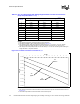
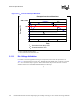
NOTES:
1. The loadline specification includes both static and transient limits except for overshoot allowed as shown in
Section 2.11.
2. This table is intended to aid in reading discrete points on Figure 2-2.
3. The loadlines specify voltage limits at the die measured at the V
CC_SENSE
and V
SS_SENSE
pins.
4. Voltage regulation feedback for voltage regulator circuits must be taken from processor V
CC
and V
SS
pins.
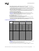
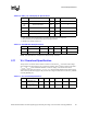
Vcc Static and Transient Tolerance
Icc (A)
Voltage Deviation from VID Setting (V)
1,2,3
Maximum Typical Minimum
0 0.000 -0.025 -0.050
5 -0.007 -0.033 -0.059
10 -0.015 -0.041 -0.068
15 -0.022 -0.049 -0.077
20 -0.029 -0.058 -0.086
25 -0.036 -0.066 -0.095
30 -0.044 -0.074 -0.104
35 -0.051 -0.082 -0.113
40 -0.058 -0.090 -0.122
45 -0.065 -0.098 -0.131
50 -0.073 -0.106 -0.140
55 -0.080 -0.114 -0.149
60 -0.087 -0.123 -0.158
65 -0.094 -0.131 -0.167
70 -0.102 -0.139 -0.176
75 -0.109 -0.147 -0.185
80 -0.116 -0.155 -0.194