
Mobile Intel Pentium 4 Processor with 533 MHz Front Side Bus


70 Mobile Intel
®
Pentium
®
4 Processor with 533 MHz System Bus Datasheet
Thermal Specifications and Design Considerations
NOTES:
1. Intel does not support or recommend operation of the thermal diode under reverse bias.
2. Characterized at 75C.
3. Not 100% tested. Specified by design characterization.
4. The ideality factor, n, represents the deviation from ideal diode behavior as exemplified by the diode
equation:
I
FW
=I
s
*(e
(qVD/nkT)
-1)
Where I
S
= saturation current, q = electronic charge, V
D
= voltage across the diode, k = Boltzmann Constant,
and T = absolute temperature (Kelvin).
5. The series resistance, R
T
, is provided to allow for a more accurate measurement of the diode junction
temperature. R
T
as defined includes the pins of the processor but does not include any socket resistance or
board trace resistance between the socket and the external remote diode thermal sensor. R
T
can be used by
remote diode thermal sensors with automatic series resistance cancellation to calibrate out this error term.
Another application is that a temperature offset can be manually calculated and programmed into an offset
register in the remote diode thermal sensors as exemplified by the equation:
T
error
= [R
T
*(N-1)*I
FWmin
]/[(nk/q)*ln N]
Where T
error
= sensor temperature error, N = sensor current ratio, k = Boltzmann Constant, q = electronic
charge.
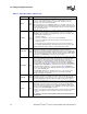
Table 25. Thermal Diode Parameters
Symbol Parameter Min Typ Max Unit Notes
I
FW
Forward Bias
Current
5 300 uA 1
n
Diode Ideality
Factor
1.0011 1.0021 1.0030 2,3,4
R
T
Series Resistance 3.64 2,3,4, 5
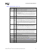
Table 26. Thermal Diode Interface
Pin Name Pin Number Pin Description
THERMDA B3 diode anode
THERMDC C4 diode cathode