
Mobile Intel Pentium 4 Processor with 533 MHz Front Side Bus


14 Mobile Intel
®
Pentium
®
4 Processor with 533 MHz System Bus Datasheet
Electrical Specifications
2.3.1 V
CC
Decoupling
Regulator solutions need to provide bulk capacitance with a low Effective Series Resistance (ESR)
and keep a low interconnect resistance from the regulator to the socket. Bulk decoupling for the
large current swings when the part is powering on, or entering/exiting low-power states, must be
provided by the voltage regulator solution. For more details on decoupling recommendations,
please refer to the appropriate platform design guidelines listed in Table 1.
2.3.2 FSB GTL+ Decoupling
The mobile Intel Pentium 4 processor integrates signal termination on the die and incorporates
high-frequency, decoupling capacitance on the processor package. Decoupling must also be
provided by the system motherboard for proper GTL+ bus operation. For more information, refer to
the appropriate platform design guidelines listed in Table 1.
2.4 Voltage Identification
The voltage set by the VID pins is the maximum voltage allowed by the processor. A minimum
voltage is provided in Table 7 and changes with frequency. This allows processors running at a
higher frequency to have a relaxed minimum voltage specification. The specifications have been
set such that one voltage regulator can work with all supported frequencies.
The mobile Intel Pentium 4 processor uses five voltage identification pins, VID[4:0], to support
automatic selection of power supply voltages. The VID pins for the mobile Intel Pentium 4
processor are open drain outputs driven by the processor VID circuitry. The VID signals rely on
pull-up resistors tied to a 3.3-V (max) supply to set the signal to a logic high level. These pull-up
resistors may be either external logic on the motherboard or internal to the Voltage Regulator.
Table 3 specifies the voltage level corresponding to the state of VID[4:0]. A 1 in this table refers to
a high-voltage level and a 0 refers to low-voltage level. If the processor socket is empty (VID[4:0]
= 11111), or the voltage regulation circuit cannot supply the voltage that is requested, it must
disable itself.
Power source characteristics must be stable whenever the supply to the voltage regulator is stable.
Refer to the Figure 14 for timing details of the power up sequence. Also refer to appropriate
platform design guidelines listed in Table 1 for implementation details.
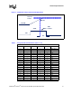
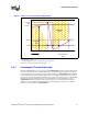
Mobile Intel Pentium 4 processor’s Voltage Identification circuit requires an independent 1.2-V
supply. This voltage must be routed to the processor VCCVID pin. Figure 1 and Table 2 show the
voltage and current requirements of the VCCVID pin.
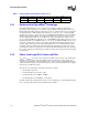
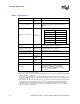
Table 2. VCCVID Pin Voltage Requirements
NOTE: This specification applies to both static and transient components. The rising edge of VCCVID must be
monotonic from 0 to 1.1 V. See Figure 1 for current requirements. In this case, monotonic is defined as
continuously increasing with less than 50 mV of peak to peak noise for any width greater than 2 nS
superimposed on the rising edge.
Symbol Parameter Min Typ Max Unit
VCCVID Vcc for voltage identification circuit -5% 1.2 +10% V