
Mobile Intel Pentium 4 Processor Supporting Hyper-Threading Technology on 90-nm Process Technology

62 Mobile Intel® Pentium® 4 Processor Supporting Hyper-Threading Technology on 90-nm Process Technology Datasheet
Thermal Specifications and Design Considerations
A processor enabled for the Intel Thermal Monitor 2 includes two operating points, each consisting
of a specific operating frequency and voltage. The first operating point represents the normal
operating condition for the processor. Under this condition, the core-frequency-to-FSB multiple
utilized by the processor is that contained in the IA32_CR_FLEX_BRVID_SEL MSR and the VID
is that specified in Table 2-8. These parameters represent normal system operation.
The second operating point consists of both a lower operating frequency and voltage. When the
TCC is activated, the processor automatically transitions to the new frequency. This transition
occurs very rapidly (on the order of 5 µS). During the frequency transition, the processor is unable
to service any bus requests, and consequently, all bus traffic is blocked. Edge-triggered interrupts
will be latched and kept pending until the processor resumes operation at the new frequency.
Once the new operating frequency is engaged, the processor will transition to the new core
operating voltage by issuing a new VID code to the voltage regulator. The voltage regulator must
support dynamic VID steps in order to support the Intel Thermal Monitor 2. During the voltage
change, it will be necessary to transition through multiple VID codes to reach the target operating
voltage. Each step will likely be one VID table entry (see Table 2-8). The processor continues to
execute instructions during the voltage transition. Operation at the lower voltage reduces the power
consumption of the processor.
A small amount of hysteresis has been included to prevent rapid active/inactive transitions of the
TCC when the processor temperature is near its maximum operating temperature. Once the
temperature has dropped below the maximum operating temperature, and the hysteresis timer has
expired, the operating frequency and voltage transition back to the normal system operating point.
Transition of the VID code will occur first, in order to insure proper operation once the processor
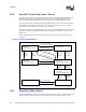
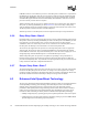
reaches its normal operating frequency. Refer to Figure 5-2 for an illustration of this ordering.
The PROCHOT# signal is asserted when a high temperature situation is detected, regardless of
whether the Intel Thermal Monitor or Intel Thermal Monitor 2 is enabled.
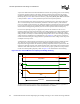
Figure 5-2. Intel Thermal Monitor 2 Frequency and Voltage Ordering
Vcc
Temperature
V
NOM
Frequency
Time
f
TM2
f
MAX
T
TM2
V
TM2
T(hysteresis)