
Intel 64 and IA-32 Architectures Software Developers Manual Volume 2B, Instruction Set Reference, N-Z

4-310 Vol. 2B
INSTRUCTION SET REFERENCE, N-Z
SIDT—Store Interrupt Descriptor Table Register
Description
Stores the content the interrupt descriptor table register (IDTR) in the destination
operand. The destination operand specifies a 6-byte memory location.
In non-64-bit modes, if the operand-size attribute is 32 bits, the 16-bit limit field of
the register is stored in the low 2 bytes of the memory location and the 32-bit base
address is stored in the high 4 bytes. If the operand-size attribute is 16 bits, the limit
is stored in the low 2 bytes and the 24-bit base address is stored in the third, fourth,
and fifth byte, with the sixth byte filled with 0s.
In 64-bit mode, the operand size fixed at 8+2 bytes. The instruction stores 8-byte
base and 2-byte limit values.
SIDT is only useful in operating-system software; however, it can be used in applica-
tion programs without causing an exception to be generated. See “LGDT/LIDT—Load
Global/Interrupt Descriptor Table Register” in Chapter 3, Intel
®
64 and IA-32 Archi-
tectures Software Developer’s Manual, Volume 2A, for information on loading the
GDTR and IDTR.
IA-32 Architecture Compatibility
The 16-bit form of SIDT is compatible with the Intel 286 processor if the upper 8 bits
are not referenced. The Intel 286 processor fills these bits with 1s; the Pentium 4,
Intel Xeon, P6 processor family, Pentium, Intel486, and Intel386 processors fill these
bits with 0s.
Operation
IF instruction is SIDT
THEN
IF OperandSize
= 16
THEN
DEST[0:15] ← IDTR(Limit);
DEST[16:39] ← IDTR(Base); (* 24 bits of base address stored; *)
DEST[40:47] ← 0;
ELSE IF (32-bit Operand Size)
DEST[0:15] ← IDTR(Limit);
DEST[16:47] ← IDTR(Base); FI; (* Full 32-bit base address stored *)
ELSE (* 64-bit Operand Size *)
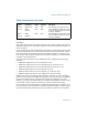
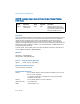
Opcode Instruction
64-Bit
Mode
Compat/
Leg
Mode Description
0F 01 /1 SIDT m Valid Valid Store IDTR to m.