
Mobile Intel Pentium 4 Processor with 533 MHz Front Side Bus

Mobile Intel
®
Pentium
®
4 Processor with 533 MHz System Bus Datasheet 31
Electrical Specifications
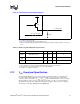
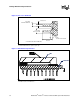
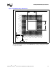
Figure 4. ITPCLKOUT[1:0] Output Buffer Diagram
NOTES:
1. See Table 13 for range of Ron.
2. The Vcc referred to in this figure is the instantaneous Vcc.
3. Refer to the ITP700 Debug Port Design Guide and the appropriate platform design guidelines for the value of
Rext.
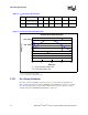
Table 14. BSEL [1:0] and VID[4:0] DC Specifications
NOTES:
1. Unless otherwise noted, all specifications in this table apply to all processor frequencies.
2. These parameters are not tested and are based on design simulations.
3. Leakage to Vss with pin held at 2.50 V.
2.12 V
CC
Overshoot Specification
The mobile Intel Pentium 4 processor can tolerate short transient overshoot events where V
CC
exceeds the VID voltage when transitioning from a high to low current load condition. This
overshoot cannot exceed VID + V
OS_MAX
(V
OS_MAX
is the maximum allowable overshoot voltage).
The time duration of the overshoot event must not exceed T
OS_MAX
(T
OS_MAX
is the maximum
allowable time duration above VID). These specifications apply to the processor die voltage as
measured across the VCC_SENSE and VSS_SENSE pins.
Vcc
Ron
Processor Package
Rext
To Debug Port
Symbol Parameter Min Max Unit Notes
1
Ron
(BSEL)
Buffer On Resistance 9.2 14.3 Ω 2
Ron
(VID)
Buffer On Resistance 7.8 12.8 Ω 2
I
HI
Pin Leakage Hi N/A 100 µA 3