
Mobile Intel Pentium 4 Processor with 533 MHz Front Side Bus

28 Mobile Intel
®
Pentium
®
4 Processor with 533 MHz System Bus Datasheet
Electrical Specifications
NOTES:
1. Unless otherwise noted, all specifications in this table apply to all processor frequencies.
2. V
IL is defined as the maximum voltage level at a receiving agent that will be interpreted as a logical low value.
3. V
IH is defined as the minimum voltage level at a receiving agent that will be interpreted as a logical high
value.
4. V
IH and VOH may experience excursions above V
CC
. However, input signal drivers must comply with the
signal quality specifications in Section 3.
5. Refer to processor I/O Buffer Models for I/V characteristics.
6. The V
CC
referred to in these specifications is the instantaneous V
CC
.
7. Vol max of 0.450 Volts is guaranteed when driving into a test load of 50 Ω as indicated in Figure 6.
8. Leakage to V
SS
with pin held at V
CC
.
9. Leakage to V
CC
with pin held at 300 mV.
10.For a platform to be forward compatible with future portable processors it must be designed to support an
GTLREF value of 0.63*Vcc -2%(min) and 0.63*Vcc+2%(max). A compatible platform is one that is designed
for some level of compatibility with future portable processors.
11.For a platform to be forward compatible with future portable processors it must be designed to support an
Ron value of 8.4 Ω (min) and 13.2 Ω (max). A compatible platform is one that is designed for some level of
compatibility with future portable processors.
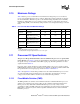
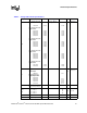
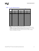
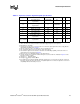
Table 10. GTL+ Signal Group DC Specifications
Symbol Parameter Min Max Unit Notes
1
GTLREF Reference Voltage 2/3 Vcc - 2% 2/3 Vcc + 2% V 10
GTLREF_COMPATIBLE Reference Voltage 0.63*Vcc - 2% 0.63*Vcc + 2% V 10
VIH Input High Voltage 1.10*GTLREF VCC V2,6
VIL Input Low Voltage 0.0 0.9*GTLREF V 3,4,6
VOH Output High Voltage N/A Vcc V 7
IOL Output Low Current N/A 50 mA 6
IHI Pin Leakage High N/A 100 µA 8
ILO Pin Leakage Low N/A 500 µA 9
R
ON Buffer On Resistance 7 11 Ω 5, 11
RON_COMPATIBLE Buffer On Resistance 8.4 13.2 Ω 5, 11