
Mobile Intel Pentium 4 Processor with 533 MHz Front Side Bus

16 Mobile Intel
®
Pentium
®
4 Processor with 533 MHz System Bus Datasheet
Electrical Specifications
2.4.1 Enhanced Intel SpeedStep
®
Technology
The mobile Intel Pentium 4 processor, when used in conjunction with the requisite Intel
SpeedStep
®
technology applet or its equivalent, supports Enhanced Intel SpeedStep technology.
Enhanced Intel SpeedStep technology allows the processor to switch between two core frequencies
automatically based on CPU demand, without having to reset the processor or change the FSB
frequency. The processor operates in two modes, the Maximum Performance mode or the Battery
Optimized mode. Each frequency and voltage pair identifies the operating mode. The processor
drives the VID[4:0] pins with the correct VID for the current operating mode. After reset, the
processor will start in Battery Optimized mode. Any RESET# assertion will force the processor to
the Battery Optimized mode. INIT# assertions ("soft" resets) and APIC bus INIT messages do not
change the operating mode of the processor. Some electrical and thermal specifications are for a
specific voltage and frequency. The mobile Intel Pentium 4 processor featuring Enhanced Intel
SpeedStep technology will meet the electrical and thermal specifications specific to the current
operating mode, and it is not guaranteed to meet the electrical and thermal specifications specific to
the opposite operating mode. The timing specifications must be met when performing an operating
mode transition.
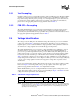
2.4.2 Phase Lock Loop (PLL) Power and Filter
V
CCA
and V
CCIOPLL
are power sources required by the PLL clock generators on the mobile Intel
Pentium 4 processor silicon. Since these PLLs are analog in nature, they require quiet power
supplies for minimum jitter. Jitter is detrimental to the system: it degrades external I/O timings as
well as internal core timings (i.e. maximum frequency). To prevent this degradation, these supplies
must be low pass filtered from V
CC
.
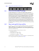
The AC low-pass requirements, with input at V
CCVID
is as follows:
• < 0.2 dB gain in pass band
• < 0.5 dB attenuation in pass band < 1 Hz
• > 34 dB attenuation from 1 MHz to 66 MHz
• > 28 dB attenuation from 66 MHz to core frequency
The filter requirements are illustrated in Figure 2. For recommendations on implementing the filter,
refer to the appropriate platform design guidelines listed in Table 1.
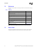
010101.600
010011.625
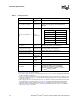
010001.650
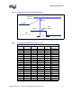
Table 3. Voltage Identification Definition (Sheet 2 of 2)