
Mobile Intel Pentium 4 Processor Supporting Hyper-Threading Technology on 90-nm Process Technology

64 Mobile Intel® Pentium® 4 Processor Supporting Hyper-Threading Technology on 90-nm Process Technology Datasheet
Thermal Specifications and Design Considerations
5.2.5 THERMTRIP# Signal Pin
Regardless of whether or not the Intel Thermal Monitor feature is enabled, in the event of a
catastrophic cooling failure, the processor will automatically shut down when the silicon has
reached an elevated temperature (refer to the THERMTRIP# definition in Table 4-3). At this point,
the front side bus signal THERMTRIP# will go active and stay active as described in Table 4-3.
THERMTRIP# activation is independent of processor activity and does not generate any bus
cycles. If THERMTRIP# is asserted, processor core voltage (Vcc) must be removed.
5.2.6 Tcontrol and Fan Speed Reduction
Tcontrol is a temperature specification based on a temperature reading from the thermal diode. The
value for Tcontrol will be calibrated in manufacturing and configured for each processor. The
Tcontrol temperature for a given processor can be obtained by reading the
IA32_TEMPERATURE_TARGET MSR in the processor. The Tcontrol value that is read from the
IA32_TEMPERATURE_TARGET MSR needs to be converted from Hexadecimal to Decimal and
added to a base value of 50 °C.
The value of Tcontrol may vary from 00 h to 1E h (0 to 30 °C).
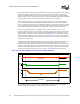
The fan must be turned on to the max rated speed of the fan or fan speed necessary to meet Tc,max
at TDP when Tdiode is at or above Tcontrol and T
C
must be maintained at or below T
C
(max) as
defined by the processor thermal specifications in Table 5-1. The fan speed may be lowered when
the processor temperature can be maintained below Tcontrol as measured by the thermal diode.
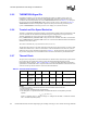
5.2.7 Thermal Diode
The processor incorporates an on-die thermal diode. A thermal sensor located on the system board
may monitor the die temperature of the processor for thermal management/long term die
temperature change purposes. Table 5-2 and Table 5-3 provide the diode parameter and interface
specifications. This thermal diode is separate from the Intel Thermal Monitor’s thermal sensor and
cannot be used to predict the behavior of the Intel Thermal Monitor.
NOTES:
1. Intel does not support or recommend operation of the thermal diode under reverse bias.
2. Characterized at 75 °C.
3. Not 100% tested. Specified by design characterization.
4. The ideality factor, n, represents the deviation from ideal diode behavior as exemplified by the diode
equation:
I
FW
= I
S
* (e
qV
D
/nkT
–1)
where I
S
= saturation current, q = electronic charge, V
D
= voltage across the diode, k = Boltzmann Constant,
and T = absolute temperature (Kelvin).
Table 5-2. Thermal Diode Parameters
Symbol Parameter Min Typ Max Unit Notes
I
FW
Forward
Bias Current
11 187 uA 1
n
Diode
Ideality
Factor
1.0083 1.011 1.0183 2, 3, 4
R
T
Series
Resistance
3.242 3.33 3.594 Ω 2, 3, 5