
Mobile Intel Pentium 4 Processor Supporting Hyper-Threading Technology on 90-nm Process Technology


Mobile Intel® Pentium® 4 Processor Supporting Hyper-Threading Technology on 90-nm Process Technology Datasheet 57
Pin Listing and Signal Descriptions
§
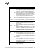
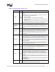
THERMTRIP# Output
In the event of a catastrophic cooling failure, the processor will automatically
shut down when the silicon has reached a temperature approximately 20 °C
above the maximum T
C
. Assertion of THERMTRIP# (Thermal Trip) indicates the
processor junction temperature has reached a level beyond which permanent
silicon damage may occur. Upon assertion of THERMTRIP#, the processor will
shut off its internal clocks (thus halting program execution) in an attempt to
reduce the processor junction temperature. To protect the processor, its core
voltage (V
CC
) must be removed following the assertion of THERMTRIP#. Driving
of the THERMTRIP# signal is enabled within 10µs of the assertion of
PWRGOOD and is disabled on de-assertion of PWRGOOD. Once activated,
THERMTRIP# remains latched until PWRGOOD is de-asserted. While the de-
assertion of the PWRGOOD signal will de-assert THERMTRIP#, if the
processor’s junction temperature remains at or above the trip level,
THERMTRIP# will again be asserted within 10µs of the assertion of PWRGOOD.
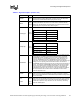
TMS Input
TMS (Test Mode Select) is a JTAG specification support signal used by debug
tools.
TRDY# Input
TRDY# (Target Ready) is asserted by the target to indicate that it is ready to
receive a write or implicit writeback data transfer. TRDY# must connect the
appropriate pins of all front side bus agents.
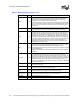
TRST# Input
TRST# (Test Reset) resets the Test Access Port (TAP) logic. TRST# must be
driven low during power on Reset.
V
CCA
Input
V
CCA
provides isolated power for the internal processor core PLLs. Refer to the
Intel® 852GME and Intel® 852PM Chipset Platforms Design Guide for complete
implementation details.
V
CCIOPLL
Input
V
CCIOPLL
provides isolated power for internal processor front side bus PLLs.
Follow the guidelines for V
CCA
, and refer to the Intel® 852GME and Intel®
852PM Chipset Platforms Design Guide for complete implementation details.
V
CCSENSE
Output
V
CCSENSE
is an isolated low impedance connection to processor core power (V
CC
).
It can be used to sense or measure voltage near the silicon with little noise.
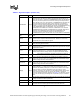
VCCVID Input
1.2 V is required to be supplied to the VCCVID pin if the platform is going to
support the processor. Refer to the Intel® 852GME and Intel® 852PM Chipset
Platforms Design Guide for more information.
VCCVIDLB Input
1.2 V is required to be supplied to the VCCVIDLB pin if the platform is going to
support the processor. Refer to the Intel® 852GME and Intel® 852PM Chipset
Platforms Design Guide for more information.
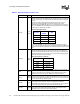
VID[5:0] Output
VID[5:0] (Voltage ID) pins are used to support automatic selection of power
supply voltages (V
CC
). These are open drain signals that are driven by the
processor and must be pulled up to 3.3 V with 1-kΩ 5% resistors. The voltage
supply for these pins must be valid before the VR can supply V
CC
to the
processor. Conversely, the VR output must be disabled until the voltage supply
for the VID pins becomes valid. The VID pins are needed to support the
processor voltage specification variations. See Table 2-2 for definitions of these
pins. The VR must supply the voltage that is requested by the pins, or disable
itself.
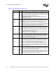
VIDPWRGD Input
The processor requires this input to determine that the VCCVID and VCCVIDLB
voltages are stable and within specification.
V
SSA
Input V
SSA
is the isolated ground for internal PLLs.
V
SSSENSE
Output
V
SSSENSE
is an isolated low impedance connection to processor core V
SS
. It can
be used to sense or measure ground near the silicon with little noise.
Table 4-3. Signal Description (Sheet 8 of 8)
Name Type Description