Guidelines
Manuals
Brands
Intel Manuals
Other
Intel Pentium Processor 3560M
41
42
43
44
45
46
47
48
49
50
Table Of Contents
1 Introduction
1.1 Design Flow
1.2 Definition of Terms
1.3 Reference Documents
2 Packaging Technology
2.1 Non-Critical to Function Solder Joints
2.2 Package Mechanical Requirements
3 Thermal Specifications
3.1 Thermal Design Power (TDP)
3.2 Thermal Specification
4 Thermal Simulation
5 Thermal Metrology
5.1 MCH Case Measurement
5.1.1 Supporting Test Equipment
5.1.2 Thermal Calibration and Controls
5.1.3 IHS Groove
5.1.4 Thermocouple Attach Procedure
6 Reference Thermal Solution
6.1 Operating Environment
6.2 Heatsink Performance
6.3 Mechanical Design Envelope
6.4 Thermal Solution Assembly
6.4.1 Extruded Heatsink Profiles
6.4.2 Retention Mechanism Responding in Shock and Vibration
6.4.3 Thermal Interface Material
6.4.4 Reference Thermal Solution Assembly Process
6.5 Reliability Guidelines
A Thermal Solution Component Suppliers
A.1 Heatsink Thermal Solution
B Mechanical Drawings
Intel® 3210 and 3200 Chipset Therma
l/Mechanical Design Guide
49
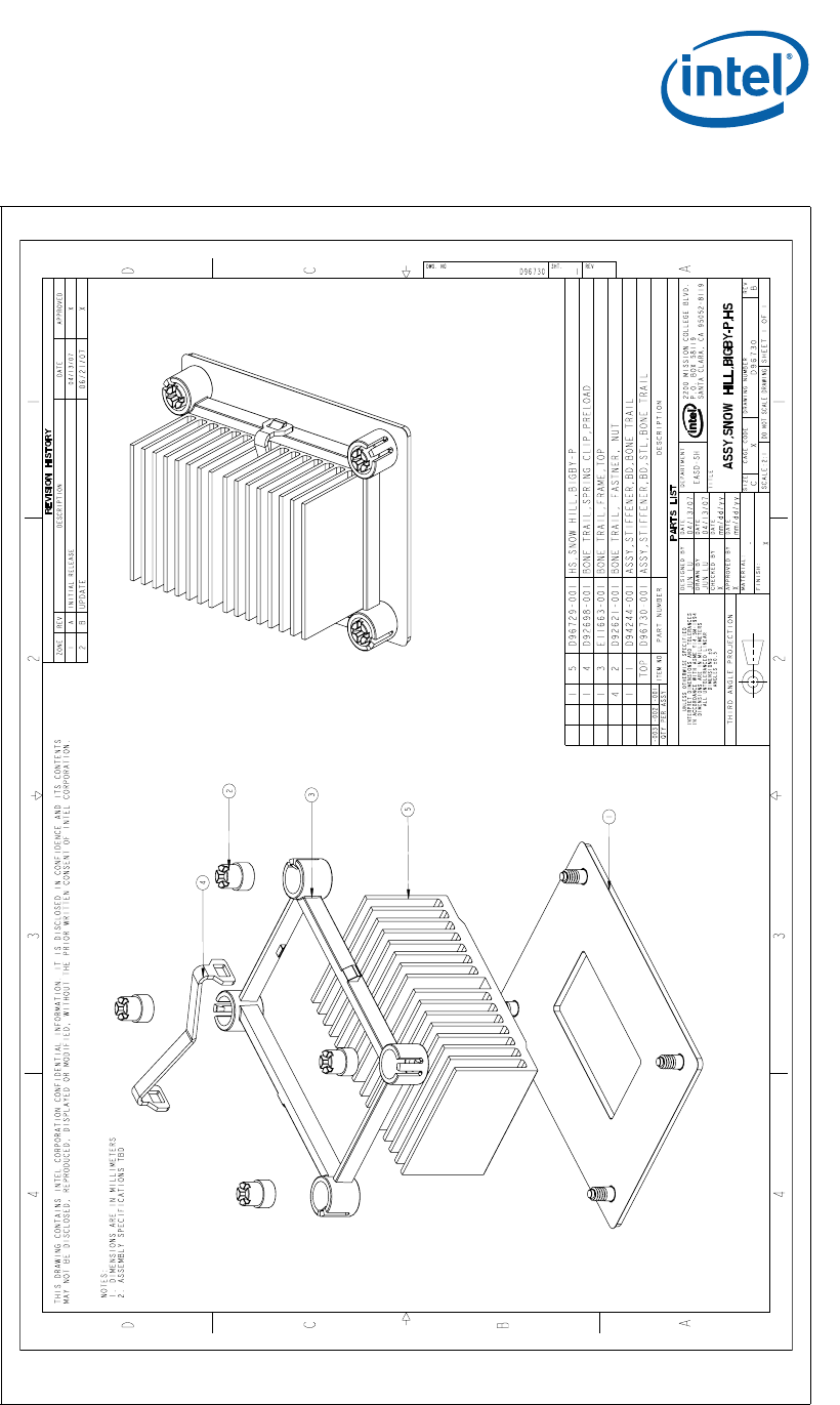
Mechanical Drawings
Figure B-4.
Intel
®
3210 and
3200 Chipset Ref
erence Thermal Sol
ution Assembly
1
...
...
47
48
49
50
51
...
...
58