Guidelines
Manuals
Brands
Intel Manuals
Other
Intel Pentium Processor 3560M
31
32
33
34
35
36
37
38
39
40
Table Of Contents
1 Introduction
1.1 Design Flow
1.2 Definition of Terms
1.3 Reference Documents
2 Packaging Technology
2.1 Non-Critical to Function Solder Joints
2.2 Package Mechanical Requirements
3 Thermal Specifications
3.1 Thermal Design Power (TDP)
3.2 Thermal Specification
4 Thermal Simulation
5 Thermal Metrology
5.1 MCH Case Measurement
5.1.1 Supporting Test Equipment
5.1.2 Thermal Calibration and Controls
5.1.3 IHS Groove
5.1.4 Thermocouple Attach Procedure
6 Reference Thermal Solution
6.1 Operating Environment
6.2 Heatsink Performance
6.3 Mechanical Design Envelope
6.4 Thermal Solution Assembly
6.4.1 Extruded Heatsink Profiles
6.4.2 Retention Mechanism Responding in Shock and Vibration
6.4.3 Thermal Interface Material
6.4.4 Reference Thermal Solution Assembly Process
6.5 Reliability Guidelines
A Thermal Solution Component Suppliers
A.1 Heatsink Thermal Solution
B Mechanical Drawings
Thermal Metrology
34
Intel® 3210 and 3200 Chipset Thermal/Mechanical Design Guide
§
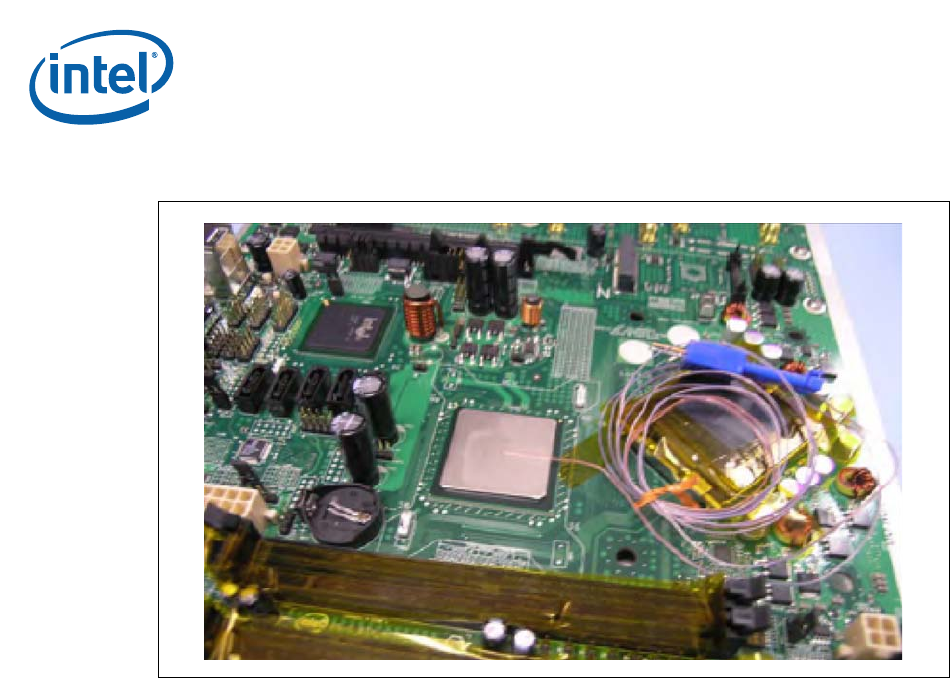
Figure 5-24. Fini
shed Th
ermocouple Installation
1
...
...
32
33
34
35
36
...
...
58