
Guide


Integrated Graphics Display Port
R
Intel
®
852GM Chipset Platform Design Guide 137
The traces associated with the LVDS Transmitter timing domain signals are differential traces
terminated across 100 ohms ± 15 % and should be routed as:
• Strip-line only.
• Isolate all other signals from the LVDS signals to prevent coupling from other sources onto the
LVDS lines.
• Use controlled impedance traces that match the differential impedance of your transmission
medium (i.e. cable) and termination resistor
• Run the differential pair trace lines as close together as possible as soon as they leave the IC, not
greater than 10 mils. This will help eliminate reflections and ensure noise is coupled as common
mode. Plus, noise induced on the differential lines is much more likely to appear as common mode,
which is rejected by the receiver.
• The LVDS Transmitter timing domain signals have a maximum trace length of 10.0 inches. This
maximum applies to all of the LVDS Transmitter signals.
• Traces must be ground referenced and must not switch layers between the GMCH and connector.
When choosing cables, it is important to remember:
• Use controlled impedance media. The differential impedance of the LVDS cable uses to connect to
the panel should be 100 Ω. Cables should not introduce major impedance discontinuities that cause
signal reflection.
• Balanced cables (twisted pair) are usually better than unbalanced cables (ribbon cable, multi-
conductor) for noise reduction and signal quality.
• Cable length must be less than 16 inches.
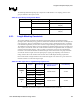
Table 52. LVDS Package Lengths
Signal Group GMCH Signal Name
Package Trace Length
(mils)
Board Length Total Trace Length
ICLKAP 503.7
ICLKAM 498.8
IYAP0 399.6
IYAM0 385.4
IYAP1 487.5
IYAM1 466.2
IYAP2 572.6
IYAM2 566.2
IYAP3 643.2
CHANNEL
A
IYAM3 637.8
ICLKAP 502.0
ICLKAM 499.1
IYBP0 359.8
CHANNEL
B
IYBM0 353.7