
Guide


Integrated Graphics Display Port
R
134 Intel
®
852GM Chipset Platform Design Guide
filtering and/or separate voltage rail may be needed to do so. On the Intel CRB, there is a place holder
for a LC filter in case there is noise present in the VCCA power rail.
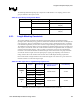
Video DAC Power Supply DC Specification: 1.50 V ± 5%
Video DAC Power Supply AC Specification:
+/- 0.3% from 0.10 Hz to 10 MHz
+/- 0.95% from 10 MHz to max pixel clock frequency
Absolute minimum voltage at the VCCA package ball = 1.40 V
Please contact your Intel Field Representative for latest AC/DC specification.
8.1.6. HSYNC and VSYNC Design Considerations
HSYNC and VSYNC signals are connected to the analog display attached to the VGA connector. These
are 3.3-V outputs from the GMCH. A 39 ohm series resistor is required before routing to the VGA
connector. Capacitors before and after the series resistor may be needed to meet the VESA VGA
connector over/undershoot specification. Please refer to Chapter 13 and 14 for for details on Intel
costomer reference board implementation. Unidirectional buffers (high impedance buffers) are required
when routing to the CRT connector to prevent potential electrical overstress and illegal operation of the
GMCH, since some display monitors may attempt to drive HSYNC and VSYNC signals back to
GMCH.
8.1.7. DDC and I2C Design Considerations
DDCADATA and DDCACLK are 3.3-V IO buffers connecting the GMCH to the monitor. To avoid
potential electrical overstress on these signals, bi-directional level-shifting devices are required. These
signals require 2.2-kΩ pull-ups (or pull-ups with the appropriate value derived from simulation) on each
of these signals. See Section 8.4 for further pullup recommendations for the DDC (GPIO) signal group.
8.2. LVDS Transmitter Interface
The Intel LVDS (Low Voltage Differential Signaling) Transmitter serializer converts up to 24 bits of
parallel digital RGB data, (8 bits per RGB), along with up to 4 bits for control (SHFCLK, HSYNC,
VSYNC, DE) into 2, 4 channel serial bit streams, for output by the LVDS transmitter.
The transmitter is fully differential and utilizes a current mode drive with a high impedance output. The
drive current develops a differential swing in the range of 250 mV to 450 mV across a 100-Ohm
termination load.
The parallel digital data is serially converted to a 7-bit serial bit stream that is transmitted over the 8
channel LVDS interface at 7x the input clock. The differential output clock channel transmits the output
clock at the input clock frequency. While the differential output channels transmit the data at the 7x
clock rate (1 bit time is 7x the input clock). The 7x serializer will synchronize and regenerate and input
clock from 35 MHz to 112 MHz. Typical operation is at 65 MHz (15.4 ns), therefore, at a 7x clock rate,
1-bit time would be 2.2 ns. With data cycle times as small as 2.2 ns, propagation delay mismatch is
critical, such that intra-channel skew (skew between the inverting and non-inverting output) must be
kept minimal.