
Guide


Integrated Graphics Display Port
R
132 Intel
®
852GM Chipset Platform Design Guide
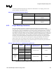
The RAMDAC channel (red, green, blue) outputs are routed as single-ended (with 37.5 ohm trace
impedance) shielded current output routes that are terminated prior to connecting to the video PI-filter
and VGA/docking connector.
Figure 64. RAMDAC Routing w/ Resistor and Analog Switch Layout Example for Docking
Connector
Complement
Output
(e.g. BLUE#)
DAC Output
(e.g. BLUE)
Via to
ground
p
lane
37.5
Ω
Trace Impedance
20 mil Space between channels
Intel 852GM
Large via or
multiple vias
straight down to
ground plane
No toggling
signals should be
routed near these
video outputs
75.0
Ω
, 1%,
1/16W, SMT metal
film resistor
75.0
Docking
Connector
Analog
Switch
37.5
Ω
Trace Impedance
VGA
Π
-Filter
20 mil Space between channels
75
Ω
Trace Impedance
NOTES:
1. The routing to the docking connector is not shown in this figure; however, this routing scheme applies to the
docking connector as well.
2. The analog switch should meet the following characteristics of C < 10pf and Ron~5ohms in order to meet VESA
analog specifications Actual value will vary depending on routing topology.
The recommended routing of the termination resistors is shown in Figure 64.