
Guide


Integrated Graphics Display Port
R
Intel
®
852GM Chipset Platform Design Guide 131
8.1.4. RAMDAC Routing Guidelines
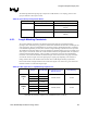
Figure 63. GMCH RAMDAC Routing Guidelines with Docking Connector
Do NOT route any high-
frequency signals in the
shaded area
RED
Red
DAC
Channel
RED#
Motherboard
GREEN
Green
DAC
Channel
GREEN#
BLUE
Blue
DAC
Channel
BLUE#
VGA
Connector
Pin 1 -
Red
Pin 2 -
Green
Pin 3 -
Blue
Place components in
Close proximity to VGA
& Docking connectors
Place ESD diodes to
minimize power rail
inductance – place C1 as
close to diodes as possible
Rset
IREF VSSDACA
VCCDACA1 VCCDACA2
1.5V
C1 C2
Place C1 and C2 as
close to package as
p
ossible
FB
C
C
1.5V
D
D
C1
37.5
Ω
im
p
edance
R1
R1
FB
C
C
FB
C
C
1.5V
D
D
C1
37.5
Ω
im
p
edance
R1
R1
FB
C
C
FB
C
C
1.5V
D
D
C1
37.5
Ω
im
p
edance
75
Ω
Routes
R1
R1
FB
C
C
Switch
Switch
75
Ω
Routes
Switch
Docking
Connector
Red
Green
Blue
75
Ω
Routes