
User's Manual
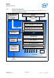

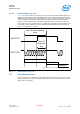
Table Of Contents
- 1.0 General Device Overview
- 2.0 Basic Operating Information
- 3.0 eUniStone Interfaces
- 4.0 General Device Capabilities
- 5.0 Bluetooth Capabilities
- 6.0 Electrical Characteristics
- 7.0 Package Information
- 8.0 Bluetooth Qualification and Regulatory Certification
- 8.1 Reference Design
- 8.2 FCC Class B Digital Devices Regulatory Notice
- 8.3 FCC Wireless Notice
- 8.4 FCC Interference Statement
- 8.5 FCC Identifier
- 8.6 European R&TTE Declaration of Conformity
- 8.7 Bluetooth Qualified Design ID
- 8.8 Industry Canada Certification
- 8.9 Label Design of the Host Product
- 8.10 Regulatory Test House
- 9.0 Assembly Guidelines
- References
- Terminology

eUniStone
PBA 31309
eUniStone Interfaces
User’s Manual Intel Public 18
Hardware Description Revision 1.0, 1-Feb-2013
3.1.1.3 UARTCTS Response Time
Figure 5 shows the UARTCTS response time. Assuming non-inverted UART signals, the
data flow stops within the “flow off response time” after UARTCTS has been set to high.
If UARTCTS goes high during the transmission of a byte (phase 1 in the figure) this byte
will be completely transmitted. While UARTCTS is high, no data will be transmitted
(phase 2). When UARTCTS goes low again, data transmission will continue (phase 3).
The maximum flow off response time is 10 UART bits (including start and stop bits). As
an example, if the UART baud rate is 115200 Baud, the maximum flow off response
time is 10 x 1/115200 s = 87 µs.
Figure 5. UARTCTS Response Time
3.2 Low Power Control
Pin P0.14 and P0.0 are optional, but strongly recommended to be used. P0.14 is used
to allow eUniStone to enter Low Power Mode (LPM). P0.0 is used by eUniStone when in
LPM to wake up the host.
HCI_UARTCTS_Response_Time.vsd
UARTCTS
UARTTXD
bit0
bit1
bit2
bit3
bit4
bit5
bit6
bit7
start
stop
bit0
start
...
phase 1
phase 2
phase 3
flow off
response
time
max. flow off response
time