
Manual


- 15 -
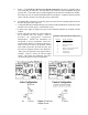
3.4 DISPLAY
The RheoVac 950 has a 2x20 alphanumeric scroll-through display that shows seven parameters for each
probe. The display shows Air In-leakage, W/A Mass Ratio, Total Mass Flow, Temperature, Pressure,
Relative Saturation, or Actual Volume Flow (as well as Time/Date, Software Version, or Serial
Number). To change the displayed parameter, press the Scroll Up or Down arrows. The display units
can be changed from English or Metric units by pressing the Units button.
If the Model 950 has two or three probes the display will show two or three serial numbers at a time,
one for each probe. The numbers will be in order, from the lowest serial number to the highest, reading
from left to right on the display. Example: 02611-1, 02611-2 and 02611-3.
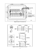
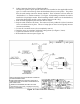
3.5 COMMUNICATIONS
Typical RheoVac 950 instruments have an Ethernet port, two serial communications choices (RS-232
or RS-422) and eight 4-20mA output signals for each probe. Each process variable is a linear, fully
temperature and pressure compensated value on any of these readable outputs. All 4-20 mA output
signals are scaled such that 4 mA represents 0% of the rated full scale value (except temperature, which
is 0°C) and 20 mA represents 100% of the rated full scale value (temperature is 100°C). The standard
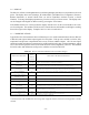
full scale values and definitions of all process variables are listed in Table III.
Table III. Process Variable Definitions and 4-20 mA Range*
PROCESS VARIABLE
4-20 mA
FULL
SCALE
VALUE
PROCESS VARIABLE DEFINITION
ACTUAL VOLUME FLOW
ACFM [m
3
/hr]
5000
[8,500]
The actual volumetric flow rate of gases leaving the condenser. It is a measure of exhauster
capacity. Decreased capacity means pump degradation.
TOTAL MASS FLOW
lbs/hr [kg/hr]
10000
[4,536]
The total mass flow rate of th e flo wing gas. N ote: this value is not a measure of air in-leak.
It is a measure of total vapor and air removal and exhauster operating capacity.
WATER VAPOR MASS FLOW
lbs/hr [kg/hr]
8000
[3,629]
The water v apor comp onen t of the flowing gas being removed from the condenser.
RheoVac PRESSURE
" Hg [mm Hg]
30
[762]
Absolute pressure at the RheoVac probe head. Should be equal to or less than turbine back
pressure.
WATER VAPOR SPECIFIC
VOLUME [cu. ft/lb]
N/A The inverse density of the water vapor present in the line. Not supplied as 4-20mA output.
WAT ER to AIR M ASS RAT IO 20 Ratio of w ater vapor flow rate to dry air flow rate. D efin es “ vacuum quality .”
RELATIVE SATURATION
[%]
100 The percent concentration of water vapor in the extraction line relative to saturation.
PARTIAL PRESSURE, WATER
"Hg [mm Hg]
N/A The partial pressure of w ater vapor in the vacuum line. Not supplied as 4-20mA outpu t.
AIR IN-LEAK
SCFM [nm
3
/hr]
100
[169.9]
Actual measure of air volume flow rate passing the RheoVac sensor head, normalized to
standard conditions (70°F, 29.9" HgA).
RheoVac TEMPERATURE
°F [°C]
212
[100]
4 mA = 0°C/32°F 20 mA = 100°C/212°F
Temperature of the flow media at the RheoVac probe head.
* See Custom Information section (Section 6) for custom units of measure.
Communication with the RheoVac unit using Intek supplied software is discussed in Appendix A of this
manual.