
Instruction Manual


- 11 -
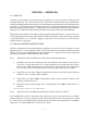
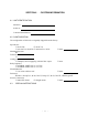
Figure 3. Set point Adjustment Components and Locations
A. Establish a flow rate at the desired trip point. The relay in standard flow switches is picked
up (energized) when the flow level is above a set point. A low level is therefore indicated in
the event of loss of power to the sensor when connected to N.C. contacts. Relay 2 will be
energized with flow below the trip level.
B. If RELAY2 is energized, adjust “Trip2” potentiometer counter clockwise until the relay de-
energizes. This is the alarm condition.
C. If RELAY2 is de-energized, adjust “Trip2” slowly clockwise just until the relay energizes.
D. If the relay cannot be made to drop out over the full range of the “Trip2” potentiometer, see
Table III.
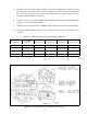
TABLE I. Alarm1 Output Configuration (all Model 400 units)
S1 Position
NC1 - COM
contacts
Relay1 State LED1 Status Flow Rate Liquid Level
LO Open energized Green Above set point Liquid
LO Closed de-energized Red Below set point Air
HI Closed de-energized Red Above set point Liquid
HI Open energized Green Below set point Air