
User Manual

-22-
I:\O FFICE\W PM A N U A L\M an200 rvb.w pd
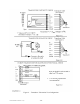
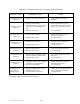
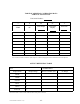
Record voltages in Table IV (last column) before contacting the factory. Be sure to use a high input
impedance digital voltmeter for the readings identified in Table IV. All readings are to be taken from
terminals BRN through R on JP2 (Figure 2) with power on and a typical flow rate flowing through the
sensor. Complete Table IV and fax it to the factory (614-895-0319).
TABLE IV. Field Check Readings
JP4WIRE
LABEL†
TRANSDUCER CABLE / WIRE
SIGNAL DEFINITION
EXPECTED
VOLTAGE [Vdc]
RECORDED
VOLTAGE
[Vdc]
+ !
O BRN Flow sensor common voltage sense
Range: !5 to
!50mV
BLU BRN Flow sensor heated RTD voltage sense Range: .2 to .4V
W BRN Flow sensor heated RTD current source Range: .2 to .4V
G BRN Flow sensor reference RTD voltage sense Range: .2 to .4V
BLK BRN Flow sensor reference RTD current source Range: .2 to .4V
R BRN Flow sensor heater <10V
† Connect + lead of volt meter to + column; Connect ! lead of volt meter to ! column.