AV Controller DHC-40.
WARNING: TO REDUCE THE RISK OF FIRE OR ELECTRIC SHOCK, DO NOT EXPOSE THIS APPARATUS TO RAIN OR MOISTURE. CAUTION: TO REDUCE THE RISK OF ELECTRIC SHOCK, DO NOT REMOVE COVER (OR BACK). NO USER-SERVICEABLE PARTS INSIDE. REFER SERVICING TO QUALIFIED SERVICE PERSONNEL.
Precautions 1. Recording Copyright—Unless it’s for personal use only, recording copyrighted material is illegal without the permission of the copyright holder. 2. AC Fuse—The AC fuse inside the unit is not user-serviceable. If you cannot turn on the unit, contact the dealer from whom you purchased this unit. 3. Care—Occasionally you should dust the unit all over with a soft cloth. For stubborn stains, use a soft cloth dampened with a weak solution of mild detergent and water.
Thank you for purchasing an Integra AV controller. Please read this manual thoroughly before making connections and plugging in the unit. Following the instructions in this manual will enable you to obtain optimum performance and listening enjoyment from your new AV controller. Please retain this manual for future reference.
Contents Introduction Important Safety Instructions ......................................... 2 Precautions....................................................................... 3 Supplied Accessories...................................................... 4 Using the Remote Controller .......................................... 4 Features ............................................................................ 6 Front & Rear Panels......................................................... 8 Front Panel...
Features Processing *1 Plus*1 • THX Ultra2 Certified • HDMI Video Upscaling (to 1080p Compatible) with Faroudja DCDi Cinema Enhancement • HDMI (Ver.1.4a with Audio Return Channel, 3D), DeepColor, x.v.
*11 Rhapsody and the Rhapsody logo are registered trademarks of RealNetworks, Inc. THX Ultra2 Plus Before any home theater component can be THX Ultra2 Plus certified, it must pass a rigorous series of quality and performance tests. Only then can a product feature the THX Ultra2 Plus logo, which is your guarantee that the Home Theater products you purchase will give you superb performance for many years to come.
Front & Rear Panels Front Panel The actual front panel has various logos printed on it. They are not shown here for clarity. The page numbers in parentheses show where you can find the main explanation for each item.
Display For detailed information, see the pages in parentheses.
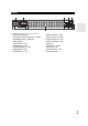
Rear Panel * DIGITAL IN COAXIAL and OPTICAL jacks GND screw RS232 terminal Terminal for control.
Remote Controller Controlling the AV Controller To control the AV controller, press Receiver to select Receiver mode. You can also use the remote controller to control Onkyo Blu-ray Disc/DVD player, CD player and other components. See “Entering Remote Control Codes” for more details (➔ 85). For detailed information, see the pages in parentheses.
About Home Theater Enjoying Home Theater Thanks to the AV controller’s superb capabilities, you can enjoy surround sound with a real sense of movement in your own home—just like being in a movie theater or concert hall. With Blu-ray Discs or DVDs, you can enjoy DTS and Dolby Digital. With analog or digital TV, you can enjoy Dolby Pro Logic IIx, DTS Neo:6, or Onkyo’s original DSP listening modes. You can also enjoy THX Surround EX (THX-certified THX speaker system recommended).
Connecting the AV Controller Connecting Your Speakers The AV controller is designed to be used with a separate multichannel power amplifier. You connect the AV controller’s PRE OUT jacks to the amplifier’s inputs, and connect your speakers to the amplifier’s speakers terminals. Speaker settings such as crossover frequency and distance are set on the AV controller.
Using Dipole Speakers You can use dipole speakers for the surround and surround back speakers. Dipole speakers output the same sound in two directions. Dipole speakers typically have an arrow printed on them to indicate how they should be positioned. The surround dipole speakers should be positioned so that their arrows point toward the TV/screen, while the surround back dipole speakers should be positioned so that their arrows point toward each other, as shown.
Bi-amping the Front Speakers The FRONT L/R and SURR BACK L/R outputs can be used with front speakers and surround back speakers, respectively, or bi-amped to provide separate tweeter and woofer feeds for a pair of front speakers that support bi-amping, providing improved bass and treble performance. • When bi-amping is used, the AV controller is able to feed up to 5.1 speakers in the main room. • For bi-amping, the FRONT L/R outputs feed the front speakers’ woofer terminals.
About AV Connections Connected image with AV components HDMI cable Other cables : Video & Audio AV controller TV, projector, etc. Blu-ray Disc/ DVD player : Video : Audio AV controller Game console TV, projector, etc. Blu-ray Disc/ DVD player • Before making any AV connections, read the manuals supplied with your AV components. • Don’t connect the power cord until you’ve completed and double-checked all AV connections.
Connecting Your Components with HDMI VCR or DVD recorder/Digital Video Recorder Game console TV, projector, etc. Personal computer Blu-ray Disc/DVD player Camcorder Satellite, cable, set-top box, etc. Connect your components to the appropriate jacks. The default input assignments are shown below. ✔: Assignment can be changed (➔ 46).
Connecting Your Components Front Rear Connect your components to the appropriate jacks. The default input assignments are shown below. ✔: Assignment can be changed (➔ 47). No. Jack Signal Components Composite video Camcorder, etc AUX Input Video Audio L/R Analog audio COMPONENT VIDEO IN 1 (BD/DVD) Component video DIGITAL Blu-ray Disc/DVD player ✔ IN 2 (CBL/SAT) Satellite, cable, set-top box, etc. ✔ IN 3 (GAME) Game console ✔ MONITOR OUT TV, projector, etc.
Note *1 Connect a turntable (MM) that has built-in a phono preamp to TV/CD IN or connect it to PHONO IN with the phono preamp turned off. If your turntable (MM) doesn’t have a phono preamp, connect to PHONO IN. If your turntable has a moving coil (MC) type cartridge, you’ll need a commercially available MC head amp or MC transformer to connect to PHONO IN. See your turntable’s manual for details. If your turntable has a ground wire, connect it to the AV controller’s GND screw.
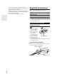
Connecting Antenna This section explains how to connect the supplied indoor FM antenna and AM loop antenna. The AV controller won’t pick up any radio signals without any antenna connected, so you must connect the antenna to use the tuner. Caution • Be careful that you don’t injure yourself when using thumbtacks. Insert the plug fully into the jack. Push. Insert wire. Release. Assembling the AM loop antenna. Thumbtacks, etc.
Which Connections Should I Use? The AV controller supports several connection formats for compatibility with a wide range of AV equipment. The format you choose will depend on the formats supported by your components. Use the following sections as a guide. Video Connection Formats Video component can be connected by using any one of the following video connection formats: composite video, S-Video, PC IN (Analog RGB), component video or HDMI, the latter offering the best picture quality.
■ “Monitor Out” setting set to “Analog” Video input signals flow through the AV controller as shown, with composite video, S-Video and PC IN (Analog RGB) sources being upconverted for the component video output. Use this setting if you connect the AV controller’s COMPONENT VIDEO MONITOR OUT to your TV. Composite video is upconverted to S-Video and S-Video is downconverted to composite video. Note that these conversions only apply to the MONITOR OUT V and S outputs, not the VCR/DVR OUT V and S outputs.
Turning On/Off the AV Controller On/Standby Standby indicator Standby On Receiver Front panel Remote controller Turning On Press On/Standby on the front panel. or Press Receiver followed by On on the remote controller. The AV controller comes on, the display lights, and the Standby indicator goes off. Pressing the remote controller’s On again will turn on any components connected via . Turning Off Press On/Standby on the front panel. or Press Receiver followed by Standby on the remote controller.
Basic Operations This manual describes the procedure using the remote controller unless otherwise specified. Selecting the Language Used for the Onscreen Setup Menus Displaying Source Information You can display various information about the current input source as follows. (Components connected to the UNIVERSAL PORT jack are excluded.) Press Receiver followed by Display repeatedly to cycle through the available information. You can determine the language used for the onscreen setup menus.
2 Muting the AV Controller Press Receiver followed by Muting. The output is muted and the MUTING indicator flashes on the display. Tip • To unmute, press Muting again or adjust the volume. • The Mute function is cancelled when the AV controller is set to Standby. ■ Video*2 You can change the following settings: “Wide Mode”, “Picture Mode”, “Brightness”, “Contrast”, “Hue” and “Saturation”. The remote controller’s Video acts as a shortcut for this menu.
Changing the Input Display When you connect an -capable Onkyo component, you must configure the input display so that can work properly. This setting can be done only from the front panel. Press My Movie, My TV, or My Music. My Movie (default): 1. The TV connected to the AV controller is turned on. 2. The Onkyo DVD player connected to the AV controller is turned on. 3. The AV controller is turned on. 4. The input selector of the AV controller is set to “BD/DVD”. 5. The player starts playback.
Changing Source Component Using Audyssey MultEQ When you want to operate the component that is not assigned as the source component, you can assign it as the source component. Using Audyssey MultEQ to create a listening environment in your home theater that all listeners will enjoy, Audyssey MultEQ takes measurements at up to six positions within the listening area. Position the microphone at ear height of a seated listener with the microphone tip pointed directly at the ceiling using a tripod.
1 2 Turn on the AV controller and the connected TV. On the TV, select the input to which the AV controller is connected. 5 Set the speaker setup microphone at the Main Listening Position , and connect it to the Setup Mic jack. Setup Mic jack 6 Speaker setup microphone The speaker setting menu appears. 3 When you’ve finished making the settings, press Enter. 7 8 Press Enter. Audyssey MultEQ® Room Correction and Speaker Setup starts.
Error Messages Changing the Speaker Settings Manually While Audyssey MultEQ® Room Correction and Speaker Setup is in progress, one of the error messages below may appear. You can manually make changes to the settings found during Audyssey MultEQ Room Correction and Speaker Setup. See also: • “Speaker Configuration” (➔ 48) • “Speaker Distance” (➔ 49) • “Level Calibration” (➔ 49) • “Equalizer Settings” (➔ 50) MultEQ: Auto Setup Ambient noise is too high.
Listening to the Radio This section describes the procedure using the buttons on the front panel unless otherwise specified. ■ Manual tuning mode 1 2 Using the Tuner With the built-in tuner you can enjoy AM and FM radio stations. You can store your favorite stations as presets for quick selection. This model changes frequency steps (➔ 59). Press and hold Tuning / . The frequency stops changing when you release the button. Press the buttons repeatedly to change the frequency one step at a time.
Presetting FM/AM Stations You can store a combination of up to 40 of your favorite FM/AM radio stations as presets. 1 2 3 4 Tune into the FM/AM station that you want to store as a preset. See the previous section. Press Memory. The preset number flashes. While the preset number is flashing (about 8 seconds), use Preset / to select a preset from 1 through 40. Press Memory again to store the station or channel. The station or channel is stored and the preset number stops flashing.
Setting Up the SiriusConnect™ Home Tuner The optional SiriusConnect Home tuner kit includes everything for easy home installation, including the SiriusConnect receiver, indoor/outdoor antenna with 21-foot cable, 8-pin mini DIN connector cable, and an AC power adapter. See the SiriusConnect Home tuner’s instructions for more information. Use the 8-pin mini DIN connector cable to connect the SiriusConnect receiver to the SIRIUS jack on the rear of the AV controller.
4 Use / to select “SAT Radio Mode”, and / to select “SIRIUS”. Pressing / cycles through the following options: None: Select if you’re not using Satellite Radio. SIRIUS: Select to use SIRIUS Satellite Radio. 5 There are three ways to select SIRIUS Satellite Radio channels: 1. Channel Search mode: select any channel. 2. Category Search mode: select channels by category. 3. Direct tuning: enter channel number. ■ Channel Search mode 7–3.
■ Selecting the previously selected channel Press Return to select the previously selected channel. Selecting Channels on the AV Controller 1 2 3 4 Press Tuner repeatedly to select “SIRIUS”. Press Tuning Mode repeatedly to select Channel Search mode or Category Search mode. 1 2 Press Receiver followed by Setup. The main menu appears onscreen. Use / to select “Hardware Setup”, and then press Enter. The “Hardware Setup” menu appears. 7. Hardware Setup 1. 2. 3. 4. 5. 6. 7.
6 7 8 9 Use / to select “Parental Lock”, and then press Enter. The channel number, channel name, and the current status are displayed. Use / to select a channel, and / “Locked” or “Unlocked”. 5 Repeat this for each of the four digits in the PIN number. If you’re entering the PIN number for the very first time, the default is “0000”. The following screen appears. to select Press Enter to save your changes, or press Return to return to the previous screen without saving.
Displaying SIRIUS Satellite Radio Information 5 Position the SiriusConnect Home antenna so that as many bars as possible (up to 3) appear on the Satellite signal strength meter. Press Display repeatedly to cycle through the available information.
Recording This section explains how to record the selected input source to a component with recording capability, and how to record audio and video from different sources. Connecting a Recording Component Recording Separate AV Sources Here you can record audio and video from completely separate sources, allowing you to overdub audio onto your video recordings. This function takes advantage of the fact that when an audio-only input source (TV/CD, PHONO, etc.
Using the Listening Modes Selecting Listening Modes See “About Listening Modes” for detailed information about the listening modes (➔ 39). Listening Mode Buttons Press Receiver first. Movie/TV, Music, Game Music Movie/TV Game THX Movie/TV button This button selects the listening modes intended for use with movies and TV. Game button This button selects the listening modes intended for use with video games. Music button This button selects the listening modes intended for use with music.
About Listening Modes The AV controller’s listening modes can transform your listening room into a movie theater or concert hall, with high fidelity and stunning surround sound. Explanatory Notes Front speakers Center speaker Surround speakers Subwoofer(s) Surround back speakers Front high speakers Front wide speakers Listening Mode ■ Input Source The following audio formats are supported by the listening mode. This is mono (monophonic) sound. This is stereo (stereophonic) sound.
Listening Modes Listening Mode Description Direct In this mode, audio from the input source is output without surround-sound processing. The “Speaker Configuration” (presence of speakers), “Sp Distance” and “A/V Sync” settings are enabled, but much of the processing set via Home is disabled. See “Advanced Setup” for more details (➔ 44). D i r ec t Stereo Input Source Speaker Layout *1 Sound is output by the front left and right speakers and subwoofer.
Listening Mode Description DTS-HD High Resolution Audio (Continued from the previous page ) DTS HD Input Source Speaker Layout *1 HR DTS-HD Master Audio DTS *1 HD MS T R DTS Express DTS Exp r ess DSD*6 DSD DTS 96/24*7 This mode is for use with DTS 96/24 sources. This is high-resolution DTS with a 96 kHz sampling rate and 24-bit resolution, providing superior fidelity. Use it with DVDs that bear the DTS 96/24 logo.
Listening Mode Description THX Founded by George Lucas, THX develops stringent standards that ensure movies are reproduced in movie theaters and home theaters just as the director intended. THX Modes carefully optimize the tonal and spatial characteristics of the soundtrack for reproduction in the home-theater environment. They can be used with 2-channel matrixed and multichannel sources. Surround back speaker output depends on the source material and the selected listening mode.
Onkyo-Original DSP Listening Modes Listening Mode Description Orchestra Suitable for classical or operatic music, this mode emphasizes the surround channels in order to widen the stereo image, and simulates the natural reverberation of a large hall.
Advanced Setup On-screen Setup Menus Common Procedures in Setup Menu This manual describes the procedure using the remote controller unless otherwise specified. Receiver MENU 1. 2. 3. 4. 5. 6. 7. 8. 9. Input/Output Assign (➔ 45) Miscellaneous (➔ 58) 1. Input/Output Assign 1. 2. 3. 4. 5.
Explanatory Notes Main Menu Speaker Setup ■ Subwoofer Yes: Select if a subwoofer is connected. No: Select if no subwoofer is connected.
1080p*2: Select this for 1080p output and video conversion as necessary. Source: Output will be according to the resolution level which was set in the “Picture Adjust” setting (➔ 55). Tip • The “Resolution” setting can be set for each “Monitor Out” setting. Note • If the “Monitor Out” setting is set to “Both”, this setting is fixed at “Auto”.
Component Video Input Digital Audio Input If you connect a video component to a component video input, you must assign that input to an input selector. For example, if you connect your Blu-ray Disc/DVD player to COMPONENT VIDEO IN 2, you must assign “IN2” to the “BD/DVD” input selector. If you’ve connected your TV to the AV controller with a component video cable, you can set the AV controller so that composite video and S-Video sources are upconverted* and output by the COMPONENT VIDEO MONITOR OUT*1.
Speaker Configuration Speaker Setup Main menu Speaker Setup Some of the settings in this section are set automatically by Audyssey MultEQ® Room Correction and Speaker Setup function (➔ 27). Here you can check the settings made by Audyssey MultEQ Room Correction and Speaker Setup function, or set them manually, which is useful if you change one of the connected speakers after using Audyssey MultEQ Room Correction and Speaker Setup function.
■ Surr Back Ch 1ch: Select if only one surround back speaker is connected. 2ch: Select if two (left and right) surround back speakers are connected. Note • If the “Surr Back” setting is set to “None” (➔ 48), this setting cannot be selected. ■ LPF of LFE (Low-Pass Filter for the LFE Channel) 80Hz, 90Hz, 100Hz, 110Hz, 120Hz With this setting, you can specify the cutoff frequency of the LFE channel’s low-pass filter (LPF), which can be used to filter out unwanted hum.
Equalizer Settings THX Audio Setup This setting is set automatically by Audyssey MultEQ® Room Correction and Speaker Setup function (➔ 27). With the Equalizer settings, you can adjust the tone of speakers individually with a 15-band equalizer. The volume of each speaker can be set (➔ 49). ■ Equalizer Manual: You can adjust the equalizer for each speaker manually. If you selected “Manual”, continue with this procedure. 1 2 Press to select “Channel”, and then use to select a speaker.
■ Preserve THX Settings Yes: Audyssey Dynamic EQ® / Audyssey Dynamic Volume® will not be active in THX listening mode. No: Audyssey Dynamic EQ / Audyssey Dynamic Volume will be active in THX listening mode depending on the setting. Note • This setting is fixed at “Yes” if “Loudness Plus” is set to “On”. THX Loudness Plus THX Loudness Plus is a new volume control technology featured in THX Ultra2 Plus™ and THX Ultra2 Plus™ Certified receivers.
Dolby ■ PLIIx Music (2ch Input) These settings apply to only 2-channel stereo sources. If you’re not using any surround back speakers, these settings apply to Dolby Pro Logic II, not Dolby Pro Logic IIx. Panorama On: Panorama function on. Off: Panorama function off. With this setting, you can broaden the width of the front stereo image when using the Dolby Pro Logic IIx Music listening mode.
LFE Level ■ Dolby Digital*1, DTS*2, Multich PCM, Dolby TrueHD, DTS-HD Master Audio, DSD*3 – dB, –20dB, –10dB, or 0dB With these settings, you can set the level of the LFE (Low Frequency Effects) channel individually for each input sources. If you find that low-frequency effects are too loud when using one of these sources, change the setting to –20 dB or – dB. *1 *2 *3 Dolby Digital and Dolby Digital Plus sources. DTS and DTS-HD High Resolution Audio sources. DSD (Super Audio CD) sources.
• When “Dynamic Volume” is set to effective, “Equalizer” is set to “Audyssey” (➔ 50) and “Dynamic EQ” is set to “On”. When “Dynamic EQ” is set to “Off”, “Dynamic Volume” becomes “Off” automatically. • When “Dynamic Volume” is set to effective, the Dynamic Vol indicator will light (➔ 9). • If Direct listening mode is selected, this setting cannot be selected.
Picture Adjust Name input area BD/DVD 4-4. Name Edit Name a n 1 { b o 2 3 } | Shift +10 A N ! [ c p e r f s g t h u i v j w k x 4 5 : Space 6 < 7 > 8 9 0 ? Back Space – Shift B C O P @ # ] Shift +10 d q CLR D E Q R $ % ; Space F S ^ , G T & . H U I V ( J W ) CLR m z ` OK All Erase K X _ / Back Space Shift l y L Y M Z ~ OK All Erase Shift*1: Switches the displayed character. Space: Enters a space character.
■ Picture Mode*1 Through: The following settings are set to the default values: “Film Mode”, “Edge Enhancement”, “Noise Reduction”, “Brightness”, “Contrast”, “Hue”, “Saturation”, “Gamma”, “Red Brightness”, “Red Contrast”, “Green Brightness”, “Green Contrast”, “Blue Brightness”, “Blue Contrast” Custom: You can set the following settings as you like: “Film Mode”, “Edge Enhancement”, “Noise Reduction”, “Brightness”, “Contrast”, “Hue”, “Saturation”, “Gamma”, “Red Brightness”, “Red Contrast”, “Green Brightness
■ Resolution*2*3 Through: Select this to pass video through the AV controller at the same resolution and with no conversion. Auto: Select this to have the AV controller automatically convert video at resolutions not supported by your TV. When the “Monitor Out” is set to “Analog”, this setting will be changed to “Through”. 480p: Select this for 480p output and video conversion as necessary. 720p: Select this for 720p output and video conversion as necessary.
Listening Mode Preset You can assign a default listening mode to each input source that will be selected automatically when you select each input source. For example, you can set the default listening mode to be used with Dolby Digital input signals. You can select other listening modes during playback, but the mode specified here will be resumed once the AV controller has been set to Standby. Main menu 1 Listening Mode Preset Use / to select the input source that you want to set, and then press Enter.
OSD Setup Tuner ■ On Screen Display This preference determines whether operation details are displayed onscreen when an AV controller function is adjusted. On: Displayed. Off: Not displayed. Even when “On” is selected, operation details may not be output if the input source is connected to an HDMI IN. For FM/AM tuning to work properly, you must specify the FM/AM frequency step used in your area. Note that when this setting is changed, all radio presets will be deleted.
■ Lip Sync Disable: HDMI lip sync disabled. Enable: HDMI lip sync enabled. The AV controller can be set to automatically correct any delay between the video and the audio, based on the data from the connected monitor. Note • This function works only if your HDMI-compatible TV supports HDMI Lip Sync. • You can check the amount of delay being applied by the HDMI Lip Sync function on the A/V Sync screen.
■ TV Control Off: TV Control disabled. On: TV Control enabled. Set to “On” when you want to control the AV controller from an -compatible TV that is connected to HDMI. Note • Do not assign the component connected with the HDMI input to the TV/CD selector when you set “TV Control” setting to “On”. Otherwise, appropriate CEC (Consumer Electronics Control) operation is not guaranteed. • Set to “Off” when the TV is not compatible or when it is unclear whether the TV is compatible or not.
Tone Control Settings Late Night You can adjust the bass and treble for the front speakers, except when the Direct or THX listening mode is selected. With the Late Night function, you can reduce the dynamic range of Dolby Digital material so that you can still hear quiet parts even when listening at low volume levels— ideal for watching movies late at night when you don’t want to disturb anyone. ■ Bass –10dB to 0dB to +10dB in 2 dB steps.
Re-EQ With the Re-EQ function, you can compensate a soundtrack whose high-frequency content is too harsh, making it more suitable for home theater viewing. ■ Re-EQ Off: Re-EQ Function off. On: Re-EQ Function on. This function can be used with the following listening modes: Dolby Digital, Dolby Digital Plus, Dolby TrueHD, Multichannel, DTS, DTS-HD High Resolution Audio, DTS-HD Master Audio, DTS Express, DSD, Dolby EX, Dolby Pro Logic IIz Height, Dolby PLIIx Movie, Neo:6 Cinema and 5.
NET/USB About NET The AV controller is network-ready, which means you can hook it up to your home network with a standard Ethernet cable and enjoy the music files stored on your computer or media server. If your network is connected to the Internet, you can also enjoy Internet radio.
Listening to Internet Radio Note To receive Internet radio, you must connect the AV controller to a network with Internet access (➔ 64). You can select Internet radio stations by connecting to the AV controller from your computer and selecting stations in your Web browser. Preset up to 40 Internet radio stations. Internet radio URLs in the following formats are supported: PLS, M3U, and podcast (RSS).
3 Enter the preset name and Internet address (URL). WEB Setup Menu Unit Information Preset Internet Radio Network set ing Save Internet Radio Information No 1 4 Name Tuner Internet Radio Refresh 1 2 URL Delete Playing Music Files on a Server This section explains how to play music files on a computer or media server through the AV controller. See “Supported Audio File Formats” to “About DLNA” for details on supported music servers and music file formats.
3 Use / to select a server, and then press Enter. A list of items on the server appears. Server1 Search Recently Added Artists Album Songs Genre Year Rating 1/8 Search You can search for music by Artist, Album, or Track. Note • The search function does not work with media servers which do not support this function. • Depending on the sharing settings in the media server, the AV controller may not able to access the content. Refer to the instruction manual of the media server.
Supported Audio File Formats For server playback, the AV controller supports the following music file formats: MP3, WMA, WAV, FLAC, Ogg Vorbis, AAC and LPCM. Not all servers support all formats. ■ MP3 • MP3 files must be MPEG-1/MPEG-2 Audio Layer 3 format with a sampling rate of 8 kHz, 11.025 kHz, 12 kHz, 16 kHz, 22.05 kHz, 24 kHz, 32 kHz, 44.1 kHz, 48 kHz and a bit-rate of between 8 kbps and 320 kbps. Incompatible files cannot be played.
Server Requirements The AV controller can play digital music files stored on a computer or media server and supports the following technologies: • Windows Media® Player 11 • Windows Media Connect 2.0 • DLNA-certified media server If the operating system of your computer is Windows Vista, Windows Media Player 11 is already installed. Windows Media Player 11 for Windows XP can be downloaded for free from the Microsoft Web site. • The computer or media server must be on the same network as the AV controller.
Using Remote Playback 1 2 Start Windows Media® Player 12. Before remote playback, setup on Windows Media Player 12 is required. On the product, press NET/USB to select the server screen. A list of media server appears. Tip • The NETWORK indicator on the product’s display lights up. When it flashes, confirm the network connection. Note • While the music files on another media server are being played, remote playback cannot be used. Stop playback on another media server.
5 When you’ve finished, press Return. The save confirmation screen appears. 7-6. Network Save Cancel 6 7 Use / to select “Save”, and then press Enter. When modifying network settings, after modifying it is necessary to execute “Save”. When you’ve finished, press Setup. The setup menu closes. Note • This procedure can also be performed on the AV controller by using its Setup, arrows, and Enter. ■ Mac Address This is the AV controller’s MAC (Media Access Control) address. This address cannot be changed.
About USB USB can be used to play music files stored on USB mass storage devices (e.g., USB flash drives and MP3 players), which can be plugged into the AV controller’s USB port. 1 Plug your USB mass storage device into the AV controller’s USB port. 2 Press NET/USB repeatedly to select the “USB” input. USB Supported Audio File Formats USB Storage For USB mass storage device playback, the AV controller supports music file formats. See “Supported Audio File Formats” (➔ 68).
Random Playback The Random function can only be set while the PLAY screen is displayed. To play songs in random order, while the list of songs is displayed, press Random. All of the songs in the current folder will be played in random order. When all of the songs in the folder have been played once, they’ll all be played again in a different random order. To cancel random playback, press Random again. Random playback supports up to 20,000 songs per folder.
Multi Zone In addition to your main listening room, you can also enjoy playback in the other room, or as we call Multi Zone. And, you can select a different source for each room. Connecting Zone 2 Connecting Your Zone 2 Speakers This setup allows 7.1-channel playback in your main listening room and 2-channel stereo playback in Zone 2, with a different source in each room. Hookup • Use an RCA audio cable to connect the AV controller’s ZONE 2 PRE OUT L/R jacks to an analog audio input on your Zone 2 amp.
Setting the Multi Zone 1 Using Zone 2 This section explains how to turn Zone 2 on and off, how to select an input source for Zone 2, and how to adjust the volume for Zone 2. Press Receiver followed by Setup. The main menu appears onscreen. Tip • If the main menu doesn’t appear, make sure the appropriate external input is selected on your TV. 2 Controlling Zone 2 from the AV controller Zone 2 indicator Use / to select “Hardware Setup”, and then press Enter. The “Hardware Setup” menu appears. 7.
Controlling Zone 2 with the Remote Controller Adjusting the Volume for Zone 2 On the remote controller, press Zone2, and then use VOL / . Standby On Zone2 Input Selector On the AV controller, press Zone 2 Level Up / Down . Muting Zone 2 On the remote controller, press Zone2, and then press Muting. Note • To control Zone 2, you must press the remote controller’s Zone2 first. • Zone2 turns red while Zone 2 is on. 1 Press Zone2, then point the remote controller at the AV controller and press On.
4 Using the 12V Triggers The 12V triggers A, B, and C can be used to turn on 12V trigger-capable components automatically when they are selected as the input source. The triggers can be set so that they activate when a connected component is selected as the input source for the main room, Zone 2 or any combination of rooms. When triggered, the output from a 12V TRIGGER OUT goes high (+12 volts and 150 milliamperes max. at TRIGGER OUT A; +12 volts and 25 milliamperes max. at TRIGGER OUT B and C).
Using the Remote Controller in Zone 2 and Multiroom Control Kits To control the AV controller with the remote controller while you’re in the Zone 2 room, you’ll need a commercially available multiroom remote control kit. • Multiroom kits are made by Niles and Xantech. These kits can also be used when there isn’t a clear line of sight to the AV controller’s remote sensor, such as when it’s installed inside a cabinet.
Controlling iPod 1 Connecting the iPod Directly to the USB Port 2 USB can be used to play music files stored on iPod/ iPhone, which can be plugged into the AV controller’s USB port. Press NET/USB repeatedly to select the USB input. Connect the USB cable that comes with the iPod/ iPhone to the USB port at the front of the AV controller. • The USB indicator lights (➔ 9) if the AV controller is able to read the iPod/iPhone. • The USB indicator flashes if the AV controller cannot read the iPod/iPhone.
Extended Mode control The content information is displayed (lists are displayed) on the on-screen, and you can select and manipulate the content while looking at the screen. Top screen list: • Playlists*4 • Artists*4 • Albums*4 • • • • • Genres*4 Songs*4 Composers*4 Shuffle Songs*5 Now Playing*6 *4 *5 *6 Displays a list. Plays all tracks in random order. Displays information about currently playing track. Connecting an Onkyo Dock *1 No.
Using the Onkyo Dock Dock is sold separately. For the latest information on the Onkyo Dock components, see the Onkyo web site at: http://www.onkyo.com Before using the Onkyo Dock components, update your iPod with the latest software, available from the Apple web site. For supported iPod models, see the instruction manual of the Onkyo Dock. UP-A1 Dock With the UP-A1 Dock, you can easily play the music, photo, or movie stored on your Apple iPod through the AV controller and enjoy great sound.
■ System Function System On When you turn on the AV controller, RI Dock and iPod turn on automatically. In addition, when the RI Dock and iPod are on, the AV controller can be turned on by pressing On/Standby. Auto Power On If you press the remote controller’s while the AV controller is on Standby, the AV controller will automatically turn on, select your iPod as the input source, and your iPod will start playback.
✔: Available buttons Press the appropriate Remote Mode first. Buttons Dock UP-A1 Dock Onkyo Dock On, Standby ✔*1 Top Menu ✔*5 / //Enter Playlist / ✔ ✔ ✔*3 ✔ ✔ ✔ Repeat ✔ ✔ Random ✔ ✔ Play Mode ✔*4 ✔*4 Display*6 ✔*2 ✔ Muting ✔ ✔ Album +/– ✔ ✔ VOL / ✔ ✔ ,, , , , , ✔ Menu Return ✔ • With some iPod models, generations and RI Docks, certain buttons may not work as expected. • For detailed operation of the iPod, please refer to the instruction manual of RI Dock.
Controlling Other Components You can use the AV controller’s remote controller (RC-770M) to control your other AV components, including those made by other manufacturers. This section explains how to enter the remote control code (with the default underlined) for a component that you want to control: DVD, TV, CD, etc. • Learn commands directly from another component’s remote controller. • Program Activities to perform a sequence of up to 32 remote control actions.
8 If you can control component, press Receiver, use / to select “Works”, and then press Enter. The “Remote Mode Setup” menu appears. If you cannot control component, press Receiver, use / to select “Doesn’t work(Try next code)” and press Enter. The next code appears. 9 You’ll need to enter a code for each component that you want to control. 2 Integra/Onkyo components that are connected via are controlled by pointing the remote controller at the AV controller, not the component.
If you want to control an Integra/Onkyo component by pointing the remote controller directly at it, use the following remote control codes: 32900: Integra/Onkyo Blu-ray Disc player 32901: Integra/Onkyo HD-DVD player 70868: Onkyo MD recorder without 71323: Onkyo CD recorder without 82990: Onkyo Dock without Note • If you connect a cassette tape deck to the TV/CD IN jack, or connect an RI Dock to the to the TV/CD IN or VCR/DVR IN or GAME IN jacks, for to work properly, you must set the Input Display acco
✔: Available buttons Press the appropriate Remote Mode first.
Learning Commands Note The AV controller’s remote controller can learn the commands of other remote controllers. By transmitting, for example, the Play command from your CD player’s remote controller, the remote controller can learn it, and then transmit the exact same command when its is pressed in the CD remote mode. This is useful when you’ve entered the appropriate remote control code (➔ 85) but some buttons don’t work as expected.
Running Macros Using Normal Macros You can program the remote controller’s Activities to perform a sequence of remote control actions. Example: To play a CD you typically need to perform the following actions: 1. Press Receiver to select the Receiver remote controller mode. 2. Press On to turn on the AV controller. 3. Press TV/CD to select the TV/CD input source. 4. Press to start playback on the CD player. You can program Activities so that all four actions are performed with just one button press.
Troubleshooting If you have any trouble using the AV controller, look for a solution in this section. If you can’t resolve the issue yourself, contact the dealer from whom you purchased this unit. If you can’t resolve the issue yourself, try resetting the AV controller before contacting the dealer from whom you purchased this unit. To reset the AV controller to its factory defaults, turn it on and, while holding down VCR/DVR, press On/ Standby.
■ Only the center speaker produces sound If you use the Dolby Pro Logic IIx Movie, Dolby Pro — Logic IIx Music, or Dolby Pro Logic IIx Game listening mode with a mono source, such as an AM radio station or mono TV program, the sound is concentrated in the center speaker. In the Mono listening mode, only the front speakers 51 output sound if the “Output Speaker” setting is set to “Center”. Make sure the speakers are configured correctly.
Video Tuner ■ There’s no picture Make sure that all video connecting plugs are pushed 16 in all the way. Make sure that each video component is properly connected. 17, 18, 80 If your TV is connected to the HDMI output, set the 45, 46 “Monitor Out” setting other than “Analog”, and select “- - - - -” in the “HDMI Input” to watch composite video, S-Video, and component video sources.
To control an Integra/Onkyo component that’s con- 85 nected via , point the remote controller at the AV controller. Be sure to enter the appropriate remote control code first. To control an Integra/Onkyo component that’s not 85 connected via , point the remote controller at the component. Be sure to enter the appropriate remote control code first. The entered remote control code may not be correct. — If more than one code is listed, try each one.
■ When performing “Audyssey MultEQ® Room Correction and Speaker Setup”, the measurement fails showing the message “Ambient noise is too high.”. This can be caused by any malfunction in your speaker unit. Check if the unit produces normal sounds. — ■ The following settings can be made for the S-Video and composite video inputs You must use the buttons on the unit to make these settings.
Specifications Amplifier Section Input Sensitivity and Impedance 200 mV/47 k (LINE) 2.5 mV/47 k (PHONO MM) Rated RCA Output Level and Impedance 200 mV/470 (PRE OUT) Maximum RCA Output Level and Impedance 4.6 V/470 (PRE OUT) Phono Overload 70 mV (MM 1 kHz 0.
About HDMI Designed to meet the increased demands of digital TV, HDMI (High Definition Multimedia Interface) is a new digital interface standard for connecting TVs, projectors, Blu-ray Disc/DVD players, set-top boxes, and other video components. Until now, several separate video and audio cables have been required to connect AV components.
Using an RIHD-compatible TV, Player, or Recorder , which stands for Remote Interactive over HDMI, is the name of the system control function found on Integra/ Onkyo components. The AV controller can be used with CEC (Consumer Electronics Control), which allows system control over HDMI and is part of the HDMI standard. CEC provides interoperability between various components, however, operation with components other than -compatible components cannot be guaranteed.
3 ■ How to connect and setup 1 Confirm the connecting and setting. 1. Connect the HDMI OUT MAIN jack to the HDMI input jack of the TV. Blu-ray Disc/DVD player, etc. HDMI connection AV controller DIGITAL AUDIO connection (OPTICAL) HDMI connection TV, projector, etc. 2. Connect the audio output from the TV to the OPTICAL IN 2 jack of the AV controller using an optical digital cable.
Video Resolution Chart The following tables show how video signals at different resolutions are output by the AV controller.
Integra Division of ONKYO U.S.A. CORPORATION 18 park Way, Upper Saddle River, N.J. 07458, U.S.A. Tel: 800-225-1946, 201-818-9200 Fax: 201-785-2650 http://www.integrahometheater.com Integra Division of ONKYO CORPORATION Sales & Product Planning Div.: 2-1, Nisshin-cho, Neyagawa-shi, OSAKA 572-8540, JAPAN Tel: 072-831-8023 Fax: 072-831-8163 En Y1005-1 SN 29400363 (C) Copyright 2010 ONKYO CORPORATION Japan. All rights reserved.