
User's Manual


3 SYSTEM COMPONENTS
13
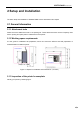
Figure 3.3 Diagram for top door
opening angle
Figure 3.4 Diagram for user operating Area
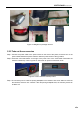
3.3 Printing Chamber Subassembly
The front door can be pulled out from the right side through releasing the electromagnetic lock by screen
operation, and then it can be seen that following components are included in the printing chamber: front
door, hot bed, dual nozzle component, brass wire brush, electromagnetic lock, magnet, door sensor,
heating and heat maintaining component, etc.
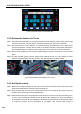
When the printing chamber is heating, please do not touch the stainless steel bottom plate and lateral
plates to avoid scald as they are in high temperature.
The four leveling rotary knobs under the hot bed are used for the manual leveling of the printing
buildplate.
Figure 3.5 Diagram for front door
opening mode
Figure 3.6 Printing chamber
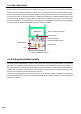
3.4 Material Chamber Subassembly
The material chamber contains two material rolls on the right and left, of which normally model materials
are installed on left material roll and the support materials are installed on the right material roll. There is
Pull
here to
open
the door
Leveling knob
Build plate
Electromagnetic
lock
Magnet
Dual nozzle
Brush
Door sensor
ON/OFF
switch
Air spring
USB-Disk
For USB
printing via PC