
User manual


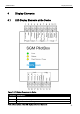


Connections and Signals SGM PilotBox
Terminal Description Description
1 12..24 VDC Power supply 12 V – 24 V DC
2 GND Ground
3 Charge Output: charging contactor control
4 Ventilation Output: Ventilation control
5 Ventilation_Feedback Input: Ventilation feedback
6 Set_MaxCurrent_0 Input: Setting the maximum charging current
7 Set_MaxCurrent_1 Input: Setting the maximum charging current
8 Release Input: Charging release
9 Act_Max_Current_0 Output: Display of the selected charging current
10 Act_Max_Current_1 Output: Display of the selected charging current
11 Plugin_Detection Output: Charging cable detection
12 Pilot + Pilot signal
13 Pilot - Reference potential for pilot signal and proximity, will be
connected to PE
14 Proximity Charging plug detection
15 Interlock_Feedback Input: Connector locking feedback
16 Interlock_1 Output: Control for connector locking contact 1
17 Interlock_2 Output: Control for connector locking contact 2
18 Interlock_NO Power supply - for connector locking
19 Interlock_NC Power supply + for connector locking when operating with a
voltage <14 V DC
Table 4: Description of the connections
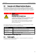
5.2 Signal Specifications
The signals of the connections 12 – 14 (Pilot +/- and Proximity) comply with the
standard EN 61851 and are not decribed in detail here.
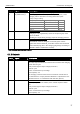
5.2.1 Inputs
Term. Signal Description
5 Ventilation_Feedback
(Ventilation_FB)
Ventilation feedback
If the vehicle indicates by signalling "State D" that a ventilation is
required for charging, the switch output for the ventilation will be
enabled. The charging contactor will be closed, but opened again
after 10 seconds, if this feedback input remains disabled. When
using ventilation, this input must be enabled by a ventilation
monitoring, if the ventilation operates properly.
16