
Datasheet


INSYS ETHERNET 5.X Technical Data
Nov-06 15
3.1.6 Digital inputs and outputs
Inputs and outputs can be set and queried via special AT commands. In remote configu-
ration mode (Telnet), this will enable the query of certain system states and the switch-
ing of certain system functions.
The function I/O tunneling will transmit the switching state at the inputs of the INSYS
Ethernet to the relay outputs of an additional INSYS Ethernet.
Input
The inputs (terminals 8 and 9) are designed as pull-up and are on HIGH in inactive, open
state. The alarm inputs are activated by connecting to ground.
LOW Active 0 to 1 V
HIGH Inactive 4 to 12 V
The input current from LOW to internal +5 V is typically 0.5 mA.
Switch output
The switch outputs (terminals 11 to 16) are potential-free relay switches.
Maximum switch voltage: 30 V (DC)
42 V (AC)
Maximum current load: 1 A (DC)
0.5 A (AC)
3.1.7 Ethernet interface 10Base-T
The 10Base-T Ethernet interface is designed as RJ45 as well as screw terminal. The lines
are connected internally according to the pin-out. A normal CAT5 cable must be used for
the connection to a network switch/hub.
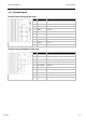
Pin-out
Terminal
Signal
Connection to RJ45
17 Rx+
3
18 Rx-
6
19 Tx+
1
20 Tx-
2
Note
When 2 Ethernet devices are directly connected, a twisted CAT5
cable must be used.