In-LineLinc™ Relay INSTEON® Remote Control In-Line On/Off Switch with Sense Owner’s Manual (rev 5.
In-LineLinc Relay – Features and Benefits............................................................................................... 3 Features..................................................................................................................................................... 3 What’s in the Box? ..................................................................................................................................... 4 Preparing to Install In-LineLinc .........................
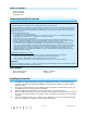
In-LineLinc Relay – Features and Benefits Congratulations on purchasing the high-quality INSTEON In-LineLinc Relay Switch with Sense. With its easy-install module, you can not only add conveniently hidden remote control to the lights wired to InLineLinc, but also automatic 120V sensing with the included (optional) Sense wire. Along with controlling other devices, In-LineLinc itself can be remotely operated from other INSTEON controllers, including other In-LineLinc modules.
What’s in the Box? - In-LineLinc Relay Quick Start Guide Six (6) wire nuts Preparing to Install In-LineLinc CAUTIONS AND WARNINGS Read and understand these instructions before installing and retain them for future reference. This product is intended for installation in accordance with the National Electric Code and local regulations in the United States or the Canadian Electrical Code and local regulations in Canada. Use indoors only.
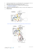
6) 7) 8) 9) 10) 11) Referring to the diagrams below, use the included wire nuts to connect the fixture’s Line, Load, Neutral, Ground and Sense wires (if using) to In-LineLinc’s corresponding wires. Enable power to the switch from the circuit breaker or fuse panel. Use In-LineLinc’s On and Off buttons to test that In-LineLinc is installed properly. The load will turn on and off. Link In-LineLinc to an INSTEON controller.
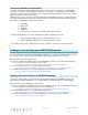
Using In-LineLinc Relay Using the ON and OFF Buttons The small button switches allows you to test the load and adjust its settings prior to final installation. - Tap ON button to turn load full-on - Tap OFF button to turn load full-off An Important Note About INSTEON Networks Split Single-Phase vs. 3-Phase Installation For the best INSTEON network performance, be sure you have properly installed at least two Access Points (#2443) or other dual-band INSTEON products.
Temporarily Disabling the Sense Wire The Sense wire may be temporarily disabled so that In-LineLinc will not automatically send INSTEON commands or control its load, regardless of change in sensor state. For example, if you are working or entertaining outside and you have motion sensors outside, temporarily disable the Sense wire to keep the lights on even when no motion is detected. NOTE: The Sense wire can only be remotely disabled from an INSTEON controller.
Linking In-LineLinc Relay as an INSTEON Controller With the Sense wire connected, you can control INSTEON responders based on the state of In-LineLinc’s load—it will automatically activate the connected load and any other linked devices when it detects 120V (such as when a motion detector is tripped), then turn them off when it no longer senses 120V. Be sure to link In-LineLinc to responders before you finish installing it in its junction box.
In-LineLinc’s status LED will start blinking. 3) Tap In-LineLinc’s Set button until it beeps again. You will have 4 minutes to complete the next step before multi-linking mode times out. 4) One at a time, press and hold each responder’s Set button about 3 seconds. 5) After you have linked all responders, tap In-LineLinc’s Set button. 6) Confirm that linking was successful by tapping In-LineLinc’s On and Off buttons. All the linked responders will respond appropriately.
X10 Settings Setting the X10 Address Most INSTEON devices are X10 ready, meaning that they can respond to X10 commands from any X10 controller. And it can send X10 commands to X10 devices. However, to operate an INSTEON device in X10 mode, you must first set up an X10 address. As it ships from the factory, or after a factory reset procedure, INSTEON devices will have no X10 address set up.
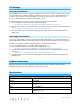
Warranty Two years, limited Operation Operation Modes INSTEON only, X10 only, INSTEON and X10 combo Combo Mode Message Order INSTEON, INSTEON cleanup, X10 LED Indicator Off when load is on and vice versa Multi-Way Circuit Support As a receiver and a controller Setup Memory Non-volatile EEPROM INSTEON Features INSTEON Address 1 hard-coded out of 16,777,216 possible INSTEON Links 417 INSTEON Powerline Frequency 131.65 KHz INSTEON Minimum Transmit Level 3.
Maximum Amps 15 amps Standby power consumption 0.68 watts Certifications Safety tested for use in USA and Canada (UL-507, CSA C22.22 #14-05) X10 Features X10 Primary Addresses 1 X10 Scene Addresses 1 X10 Status Response Supported X10 Resume Dim Supported by setting local on-level to zero X10 Powerline Frequency 120 KHz X10 Minimum Transmit Level 3.
Responder. INSTEON controller. unlinking In-LineLinc from it. The light turned on by itself. Install a powerline signal blocker in your home to keep X10 signals from neighboring homes Another controller, a timer or from interfering. Consider not using In-LineLinc stray X10 signals triggered In- in X10 mode. LineLinc. If the above doesn't work, perform a factory reset. See Factory Reset. Install a powerline noise filter (such as FilterLinc) between the load and In-LineLinc.
Certification and Warranty Certification This product has been thoroughly tested by ITS ETL SEMKO, a nationally recognized independent third-party testing laboratory. The North American ETL Listed mark signifies that the device has been tested to and has met the requirements of a widely recognized consensus of U.S.