
Garbage Disposal User Manual


8
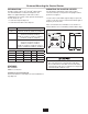
MS-5 Wiring Diagram
P/N 14356A
208 - 230 V
1-phase
1/2 to 2 HP
Call Toll Free 1-800-845-8345
for the nearest InSinkErator
Authorized Service Agency or
to reach Technical Support.
ELECTRICAL SHOCK
• Turn off the electrical supply to the disposer before
attempting any work on it. Use a voltmeter or
circuit tester to ensure that power is off.
• Installation must conform to local electrical codes.
• All control centers and disposers must be carefully
and permanently grounded.
• A properly fused disconnect must be installed at
the electrical supply source for the control center.
PROPERTY DAMAGE
• Ensure that the control center voltage and phase
match the disposer motor and electrical supply.
Check nameplates on disposers and control
centers for voltage and phase specification.
• The disposer motor wiring connection is shown in
the disposer terminal box.
1L1 3L2 5L3 13NO
2T1 4T2 6T3 14NO
A2
11
2
A1 A2
L1
L2
L3
L1
L2
INCOMING
POWER
SUPPLY
TO
PANEL
GROUND
WATER SOLENOID VALVE
DISPOSER
MOTOR
2
3
4
5
6
7
1
-2
-1
-4
-3