
User Manual


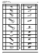

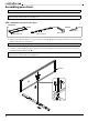
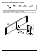

Table Of Contents
- Contents
- IMPORTANT SAFEGUARDS
- Features
- Package contents
- Tools needed
- Assembling your stand
- STEP 1: Attach the top panel to the spine
- STEP 2: Attach the top shelf support to the top panel and spine
- STEP 3: Attach the middle shelf to the spine
- STEP 4: Attach the bottom shelf to the spine
- STEP 5: Align and attach the right side frame to the shelves
- STEP 6: Attach the right side frame to the top panel
- STEP 7: Attach the left side frame to the shelves
- STEP 8: Fasten the left side frame to the top panel
- Mounting the TV using the swivel configuration
- STEP 1: Attach the swivel bracket to the mounting frame
- STEP 2: Attach the swivel bracket assembly to the spine
- STEP 3: Attach the cable clips
- STEP 4: Select the correct bolts, washers, and spacers for your TV
- STEP 5: Determine whether your TV has a flat back or an irregular or obstructed back or a curved screen
- STEP 6: Option 1 - Mounting brackets on a TV with a flat back
- STEP 6: Option 2: Mounting bracket on a TV with an irregularly shaped or obstructed back or a curved screen TV
- STEP 7: Attach the TV to the mounting frame on the swivel bracket
- STEP 8: Adjusting the tilt
- STEP 9: Position your TV stand and install the tipping restraint hardware kit
- Mounting the TV using the wall-mount configuration
- Mounting the TV using the tabletop configuration
- Maintaining your TV stand
- Specifications
- ONE-YEAR LIMITED WARRANTY

www.insigniaproducts.com
6
Hardware
LABEL STAND PART QTY. LABEL STAND PART QTY.
L 4 V 1
M 13 W 2
N 4 X 1
O 12 Y 1
P 2 Z 1
Q 29 AA 4
R 29 BB 4
S 4 CC 4
T 4 DD 4
U 4 EE 4
Bolt 1/2" (12.7 mm)
Plastic end cap
Bolt 5/8" (15.9 mm)
Hex key 4 mm
Bolt 1"’ (25.4 mm)
Hex key 4.8 mm
Bolt 1 1/4" (31.6 mm)
Touch-up pen
Bolt 1 3/4" (44.5 mm)
Tipping restraint hardware kit
Lock washer
Bolt M4 × 12 mm
Flat washer
Bolt M4 × 30 mm
Lag bolt
Bolt M5 × 12 mm
Concrete anchor
Bolt M5 × 30 mm
Large flat washer
Bolt M6 × 12 mm