INSTALLATION GUIDE 1.6 Cu. Ft. Over-the-Range Microwave NS-OTR16SS9 / NS-OTR16WH9 Before using your new product, please read these instructions to prevent any damage.
Contents Introduction . . . . . . . . . . . . . . . . . . . . . . . . . . . . . . . . . . . . . . . . . . . . . . . . . . . . . . . . . . . . . . . . . . . . . . . . . . . . . . . . . . . . . . . . . . 3 BEFORE YOU BEGIN . . . . . . . . . . . . . . . . . . . . . . . . . . . . . . . . . . . . . . . . . . . . . . . . . . . . . . . . . . . . . . . . . . . . . . . . . . . . . . . . . . . 3 IMPORTANT SAFETY INSTRUCTIONS . . . . . . . . . . . . . . . . . . . . . . . . . . . . . . . . . . . . . . . . . . . . . . .
NS-OTR16SS9 / NS-OTR16WH9 Introduction Congratulations on your purchase of a high-quality Insignia product. Your NS-OTR16SS9 / NS-OTR16WH9 represents the state of the art in microwave design and is designed for reliable and trouble-free performance. This installation guide will show you how to install your new over-the-range microwave. BEFORE YOU BEGIN Read these instructions completely and carefully. • IMPORTANT – Save these instructions for local inspector’s use.
Package contents • • • • • • • 1.6 cu. ft. over-the-range microwave Turntable (with ring) Installation parts (“Parts” on page 4) Installation hardware (see “Hardware” on page 4) Mounting templates (2) Installation Guide User Guide Parts Make sure that you have all the parts necessary to install your new microwave. Mounting plate (Qty. 1) Grease filters (Qty. 2) Exhaust adapter (Qty. 1) Hardware HARDWARE QTY.
NS-OTR16SS9 / NS-OTR16WH9 Before you install Read these instructions completely before installing your microwave. Make sure that your space meets the mounting requirements and that you’ve gathered all needed tools and materials.
Mounting requirements • The space between the cabinets must be 30 in. (76.2 cm) wide. If the space between the cabinets is more than 30 in. (76.2 cm), you’ll need filler material to fill the gap between the microwave and cabinets. • This microwave is for installation over ranges up to 36 in. (91.4 cm) wide. • If installing the microwave beneath smooth, flat cabinets, make sure that you leave enough space for the power cord clearance.
NS-OTR16SS9 / NS-OTR16WH9 Exhaust requirements Use this section if you plan to vent your microwave outside (top or back exhaust). If you plan to recirculate the air back into the room, skip to “Removing your microwave” on page 9. When installing exhaust vents: • Use the most direct route with as few elbows/transitions as possible. This helps prevent blockages and ensures that the exhaust is being vented correctly. • Your microwave is designed to mate with a standard 3-1/4” × 10” rectangular duct.
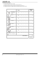
Equivalent duct length table To calculate your equivalent duct length: 1 Write the number of sections used for each of the duct pieces. 2 Multiply the number used by the equivalent length for each duct piece. 3 Add the total equivalent lengths together. This number must be less than 140 ft. Duct Pieces Rectangular-toround transition adapter Equivalent Length × Number Used = Total Equivalent Length 5 ft. × ( ) = ft. 40 ft. × ( ) = ft. 10 ft. × ( ) = ft. 5 ft. × ( ) = ft.
NS-OTR16SS9 / NS-OTR16WH9 Removing your microwave 1 Remove the upper foam from the box. Keep all the accessories. 2 Pull the microwave out of the box. 3 Remove and throw away the plastic bags. Foam Plastic bag Microwave Box 4 Remove the mounting plate from the upper foam. www.insigniaproducts.
Installing your microwave Step 1: Find the wall studs WARNING: Your microwave must be connected to at least one wall stud. 1 Using an edge-to-edge stud finder, locate the edges of the wall stud(s) within the opening. WARNING: The center of any adjacent wall studs should be 16" or 24" from this mark. 2 Mark the center of each stud, and then draw a vertical line down the center of each stud. Wall stud Center of the wall stud You’ll need: Pencil Edge-to-edge stud finder 10 Ruler or tape measure www.
NS-OTR16SS9 / NS-OTR16WH9 Step 2: Align the rear wall template Note: If the rear wall template is damaged or unusable, measure and mark the wall with the dimensions at the end of this step. 1 Use a level to make sure that the bottom of the cabinet is level. 2 Draw a vertical line down the center of the wall in the mounting space. This is where the center of your template will be. 3 Draw a horizontal line at the height of the front of your cabinet. This is where the top of your template will be.
5 Tape the template in place so that it is centered on the vertical line and the top edge is aligned with the horizontal line. Top of the template aligned with the horizontal line Vertical line in the center 6 Mark points A and B on the wall with a pencil. 7 If the stud is on the center line, mark point C on the wall with a pencil. OR If the stud is not on the center line, mark two holes on either side of point C that align with the studs. 8 Drill holes through the template at points you marked.
NS-OTR16SS9 / NS-OTR16WH9 Step 3: Select a ventilation type This microwave is designed for three types of ventilation. Select the type of ventilation you want to use, then go to the corresponding page. Note: This microwave is shipped assembled for top exhaust ventilation. Option A - Outside top exhaust (vertical duct): See page 14 Adapter Option B - Outside back exhaust (horizontal duct): See page 22 Note: If a wall stud is within 6 in. (15.
Step 4: Option A - Attach the mounting plate to the wall Note: Depending on your stud locations, your installation may look different. You should insert toggle bolts into drywall and wood screws into studs. 1 Remove the rear wall template. 2 Remove the mounting plate from the upper foam. 3 Insert the toggle bolt(s) through the front of the mounting plate into the hole(s) that are not going into a stud, and then attach the toggle wings ¾" onto each bolt.
NS-OTR16SS9 / NS-OTR16WH9 5 Insert wood screw(s) through the mounting plate and into the hole(s) drilled in the stud(s), then tighten both the wood screw(s) and toggle bolt(s) with a Phillips screwdriver to mount the plate. Make sure that the plate is centered before tightening fully. CAUTION: Be careful to avoid pinching your fingers between the back of the mounting plate and the wall.
Step 5: Option A - Preparing the top cabinet You need to drill holes for the top support screws, a hole large enough for the power cord to fit through, and a cutout large enough for the exhaust adapter. 1 Turn off the power to the outlet in the cabinet. 2 Remove everything from the cabinet. 3 Trim the Top Cabinet Template along the dotted line. 4 If the bottom of your cabinet is recessed and the template is too large, trim the edges to fit. Your template should fit snugly inside the space with no overhang.
NS-OTR16SS9 / NS-OTR16WH9 11 If you have recessed cabinets: • Make two filler blocks out of scrap wood pieces the size of shaded areas G and H. They must be as thick as the depth of the cabinet recess. • Drill 5/8" holes in the filler blocks to align with points D and E. • Align the blocks with the corresponding holes in the cabinet. They should be at the same level as the bottom edge of the cabinet frame.
Step 6: Option A - Insert the exhaust adapter 1 Set the microwave in its upright position, with the top facing up. 2 Remove any tape securing the damper and make sure that the damper pivots easily. Damper Back of microwave 3 Insert the exhaust adapter into the slots next to the ventilation and secure with a sheet metal screw. You’ll need: Exhaust adapter 18 www.insigniaproducts.
NS-OTR16SS9 / NS-OTR16WH9 Step 7: Option A - Mount the microwave CAUTIONS: • For easier installation and personal safety, we recommend that two people install this product because of the weight. We highly recommend professional installation if any electrical or carpentry work is required. • Do not grip or use the handle during installation. • To keep the power cord tight while mounting the microwave oven, thread the power cord through the hole in the bottom of the cabinet.
4 While holding the microwave up against the wall and cabinet fully tighten the outer two screws. 5 Fit the two grease filters into the openings underneath your microwave. BOTTOM You’ll need: Nylon grommet (for metal cabinets) 20 Self-aligning machine screws Phillips screwdrivers Grease filters www.insigniaproducts.
NS-OTR16SS9 / NS-OTR16WH9 Step 8: Option A - Connecting ductwork 1 Open the cabinet and slide the exhaust adapter front-to-back or side-to-side to adjust. Blower plate Exhuast adapter Damper Back of microwave 2 Extend the house duct down to connect to the exhaust adapter. 3 Seal the exhaust duct joints with duct tape. House duct 4 You’re finished! Skip to “Before using your microwave” on page 41. You’ll need: Duct tape www.insigniaproducts.
Step 4: Option B - Cutting a vent opening 1 Use a saber or keyhole saw to cut out the shaded area K through the rear wall. Note: If a wall stud is within 6 in. (15.2 cm) of the vertical center line, you cannot use this installation option. Saw 2 Remove the rear wall template. You’ll need: Saw (saber, hole, or keyhole) 22 www.insigniaproducts.
NS-OTR16SS9 / NS-OTR16WH9 Step 5: Option B - Attach the mounting plate to the wall Note: Depending on your stud locations, your installation may look different. You should insert toggle bolts into drywall and wood screws into studs. 1 Remove the rear wall template. 2 Remove the mounting plate from the upper foam. 3 Insert the bolt(s) through the front of the mounting plate into the hole(s) that are not going into a stud, and then reattach the toggle wings ¾" onto each bolt.
5 Insert wood screw(s) through the mounting plate and into the hole(s) drilled in the stud(s), then tighten both the wood screw(s) and toggle bolt(s) with a Phillips screwdriver to mount the plate. Make sure that the plate is centered before tightening fully. CAUTION: Be careful to avoid pinching your fingers between the back of the mounting plate and the wall. Toggle bolt Toggle wing Wall Mounting plate You’ll need: Toggle bolts Wood screws Mounting plate (Qty. 1) 24 www.insigniaproducts.
NS-OTR16SS9 / NS-OTR16WH9 Step 6: Option B - Preparing the top cabinet You need to drill holes for the top support screws and a hole large enough for the power cord to fit through. 1 Turn off the power to the outlet in the cabinet. 2 Remove everything from the cabinet. 3 Trim the Top Cabinet Template along the dotted line. 4 If the bottom of your cabinet is recessed and the template is too large, trim the edges to fit. Your template should fit snugly inside the space with no overhang.
10 If you have recessed cabinets: • Make two filler blocks out of scrap wood pieces the size of shaded areas G and H. They must be as thick as the depth of the cabinet recess. • Drill 5/8" holes in the filler blocks to align with points D and E. • Align the blocks with the corresponding holes in the cabinet. They should be at the same level as the bottom edge of the cabinet frame.
NS-OTR16SS9 / NS-OTR16WH9 Step 7: Option B - Adapt the microwave blower for outside back exhaust 1 Remove and save the five screws that hold the blower unit in the microwave. Blower unit Back of microwave Blower plate and adapter screws Blower motor screw Blower plate and adapter screw 2 Carefully pull out the blower unit. The wires will extend far enough to let you adjust the blower unit. Do not disconnect the wires. WARNING: Do not pull or stretch the blower unit wiring.
4 Turn the blower unit 180° so that the fan blade openings are facing out the back of the microwave. AFTER BEFORE 5 Place the blower unit back into the opening. The blower unit exhaust openings should match the exhaust openings on back of the microwave. Fan blade openings facing the back 6 Slide the exhaust adapter into the guides on the back of the microwave and push in until it is aligned with the blower motor screw holes, then secure with the blower motor screws.
NS-OTR16SS9 / NS-OTR16WH9 8 Secure the blower plate and exhaust adapter with the remaining screws you removed previously. Blower plate Blower plate and adapter screws Exhaust adapter You’ll need: Phillips screwdrivers Tin snips www.insigniaproducts.
Step 8: Option B - Mount the microwave CAUTIONS: • For easier installation and personal safety, we recommend that two people install this product because of the weight. We highly recommend professional installation if any electrical or carpentry work is required. • Do not grip or use the handle during installation. • To keep the power cord tight while mounting the microwave oven, thread the power cord through the hole in the bottom of the top cabinet.
NS-OTR16SS9 / NS-OTR16WH9 4 While holding the microwave up against the wall and cabinet fully tighten the outer two screws. 5 Fit the two grease filters into the openings underneath your microwave. BOTTOM 6 You’re finished! See “Before using your microwave” on page 41 You’ll need: Nylon grommet (for metal cabinets) Self-aligning machine screws Phillips screwdrivers Grease filters www.insigniaproducts.
Step 4: Option C - Attach the mounting plate to the wall Note: Depending on your stud locations, your installation may look different. You should insert toggle bolts into drywall and wood screws into studs. 1 Remove the rear wall template. 2 Remove the mounting plate from the upper foam. 3 Insert the bolt(s) through the front of the mounting plate into the hole(s) that are not going into a stud, and then reattach the toggle wings ¾" onto each bolt.
NS-OTR16SS9 / NS-OTR16WH9 4 Place the mounting plate against the wall and insert the toggle wings into the holes you drilled in the drywall. Pull the mounting plate away from the wall to help tighten the toggle wings. 5 Insert wood screw(s) through the mounting plate and into the hole(s) drilled in the stud(s), then tighten both the wood screw(s) and toggle bolt(s) with a Phillips screwdriver to mount the plate. Make sure that the plate is centered before tightening fully.
Step 5: Option C - Preparing the top cabinet You need to drill holes for the top support screws and a hole large enough for the power cord to fit through. 1 Turn off the power to the outlet in the cabinet. 2 Remove everything from the cabinet. 3 Trim the Top Cabinet Template along the dotted line. 4 If the bottom of your cabinet is recessed and the template is too large, trim the edges to fit. Your template should fit snugly inside the space with no overhang.
NS-OTR16SS9 / NS-OTR16WH9 10 If you have recessed cabinets: • Make two filler blocks out of scrap wood pieces the size of shaded areas G and H. They must be as thick as the depth of the cabinet recess. • Drill 5/8" holes in the filler blocks to align with points D and E. • Align the blocks with the corresponding holes in the cabinet. They should be at the same level as the bottom edge of the cabinet frame.
Step 6: Option C - Adapting blower for recirculation 1 Remove and save the five screws that hold the blower unit in the microwave. Blower unit Back of microwave Remove blower plate and adapter screws and save Remove blower motor screws and save Remove blower plate and adapter screw and save 2 Carefully pull out the blower unit. The wires will extend far enough to let you adjust the blower unit. Do not disconnect the wires. WARNING: Do not pull or stretch the blower unit wiring.
NS-OTR16SS9 / NS-OTR16WH9 4 Place the blower unit back into the opening. The blower unit exhaust openings should match the exhaust openings toward the front of the microwave. Fan blade openings facing the front www.insigniaproducts.
5 Secure the blower unit in the microwave with the remaining screws you previously removed. Note: Make sure that the damper hinge is at the top and that it can swing freely. . Back of microwave Remove blower plate and adapter screws and save Remove blower motor screws and save Remove blower plate and adapter screw and save You’ll need: Phillips screwdrivers 38 www.insigniaproducts.
NS-OTR16SS9 / NS-OTR16WH9 Step 7: Option C - Mount the microwave CAUTIONS: • For easier installation and personal safety, we recommend that two people install this product because of the weight. We highly recommend professional installation if any electrical or carpentry work is required. • Do not grip or use the handle during installation. • To keep the power cord tight while mounting the microwave oven, thread the power cord through the hole in bottom of the top cabinet.
4 While holding the microwave up against the wall and cabinet fully tighten the outer two screws. 5 Fit the two grease filters into the openings underneath your microwave. BOTTOM 6 You’re finished! Skip to “Before using your microwave” on page 41. You’ll need: Nylon grommet (for metal cabinets) 40 Self-aligning machine screws Phillips screwdrivers Grease filters www.insigniaproducts.
NS-OTR16SS9 / NS-OTR16WH9 Before using your microwave Note: Keep these installation instructions for the local inspector’s use. 1 2 3 4 Make sure that all packing material has been removed from the microwave. Install the turntable and ring inside your microwave. See your User Guide for more information. Plug the power cord into a dedicated 20 amp electrical outlet. Turn your circuit breaker back on. www.insigniaproducts.
Template dimensions Rear wall template dimensions If your rear wall template is unusable, drill using the dimensions below: 16.5 in. (41.9 cm) 30 in. (76.2 cm) 42 www.insigniaproducts.
NS-OTR16SS9 / NS-OTR16WH9 Top cabinet template dimensions If your top cabinet template is unusable, drill using the dimensions below: 11 in. (27.9 cm) 30 in. (76.2 cm) www.insigniaproducts.
Obtaining replacement parts Call Insignia Customer Service at 1-877-467-4289. Specifications Model Rated voltage Rated input power Rated output power Microwave capacity Turntable diameter External dimensions (HxWxD) Internal dimensions (HxWxD) Certifications Power cord length Net weight NS-OTR16SS9 / NS-OTR16WH9 120V / 60 Hz 1550W 1000W 1.6 cu. ft. 12.4 in. (31.5 cm) 16.9 x 29.9 x 17.6 in. (42.9 x 75.9 x 44.6 cm) 10.2 x 21.1 x 14.6 in. (25.9 x 54.1 x 37.1 cm) UL and CUL approved 39.8 in. (101 cm) 52.
NS-OTR16SS9 / NS-OTR16WH9 ONE-YEAR LIMITED WARRANTY Definitions: The Distributor* of Insignia branded products warrants to you, the original purchaser of this new Insignia-branded product (“Product”), that the Product shall be free of defects in the original manufacturer of the material or workmanship for a period of one (1) year from the date of your purchase of the Product (“Warranty Period”).
www.insigniaproducts.com 1-877-467-4289 (U.S. and Canada) or 01-800-926-3000 (Mexico) INSIGNIA is a trademark of Best Buy and its affiliated companies. Distributed by Best Buy Purchasing, LLC 7601 Penn Ave South, Richfield, MN 55423 U.S.A. ©2019 Best Buy. All rights reserved. Made in China.