
User Manual


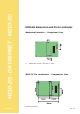
Table Of Contents
- Content
- CHAPTER 1 M210-2G description
- Chapter 2 M210-2G connection
- Chapter 3 Command interface reference manual
- Chapter 4 User's Guide
- appendix A How to load a key in A coupler
- appendix B ERROR CODE

M210-2G - DATASHEET - M210-2G
DS - 8
Version 1.1
System Integration
Diagrams below show coupler’s block diagram and architecture of 2 types of applications:
1. Coupler is integrated in a stand alone reader (access control, data collection...)
2. Coupler is connected to a computer
Ant
Power supply
Receiver
Emitter
Com interfaces
Processor
M210-2G Block Diagram
Stand Alone
Application
code
Power Supply
Microcontroller
Coupler
Application data
memory
External I/O
drivers
PicoTag
transponder
Example 1: Stand Alone Reader Structure