Inseego WavemakerTM PRO 5G Outdoor Modem FW2000e Installation Guide
About the FW2000e Description The 5G Outdoor Modem FW2000e delivers high-speed data over both 5G and 4G LTE networks using a proprietary high-gain antenna array. The FW2000e connects to the optimal cellular network and provides data connectivity to the existing in-building network. Durability The FW2000e has an environmental rating of IP67 for water and dust ingress and can operate within a temperature range of -30°C to 70°C (-22 to 158°F).
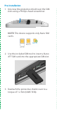
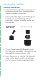
Pre-Installation 1. Unscrew the protective shield over the SIM slots using a Phillips-head screwdriver. NOTE: This device supports only Nano SIM cards. 2. Use the included SIM tool to insert a Nano 4FF SIM card into the appropriate SIM slot. 3. Reattach the protective shield cover to a torque of 1.2 Nm (0.885 ft/lb).
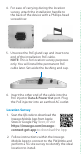
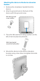
. For ease of carrying during the location survey, attach the installation handle to the back of the device with a Phillips-head screwdriver. 5. Unscrew the PoE gland cap and insert one end of the installation PoE cable. NOTE: This is for location survey purposes only. You will install the permanent PoE cable later. Set aside the bushing and cap. 6. Insert the other end of the cable into the PoE injector Data & Power Out port. Plug the PoE injector into an earthed AC outlet. Location Survey 1.
Installing the FW2000e Installing the PoE cable 1. Remove the installation PoE cable used for the location survey from the device using needle nose pliers or tweezers. 2. Remove the rubber pin from the PoE gland bushing and assemble the gland cap, putting the bushing inside the spacer and into the cap. Rubber pin and gland bushing Gland cap assembly 3. Thread the permanent PoE cable through the hole in the assembled PoE gland cap and attach a RJ45 connector to the cable. 4.
Attaching the device to the device elevation bracket 1. Remove the installation handle from the device. 2. Attach a ground wire to the back of the device with the ground screw. M5 10mm ground screw / washer 3. Place the M6 external locking washers on the M6 21mm bracket mount bolts. M6 21mm bracket mount bolt and washer 4. Mount the device to the device elevation bracket using a hex driver to tighten the bolts to 2.0 Nm.
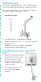
Installing the mount The mount is adjustable and can be mounted on vertical, horizontal, and slanted exterior surfaces. The mount is attached using the four roof mount lag screw in the corners of the base. Roof mount lag screw 1. Pre-drill holes in the surveyed location. 2. Attach the mount using a hex driver to tighten the lag screws. NOTE: Concrete anchors are provided if mounting to concrete or brick. Securing the device elevation bracket to the mount 1.
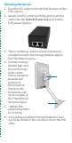
Orienting the device 1. Run the PoE cable to the desired location of the PoE injector. 2. Attach a RJ45 connector fitting and insert the cable into the Data & Power Out port on the PoE power injector. 3. Take a racheting socket wrench and device/ smartphone with the Inseego Mobile App to the FW2000e location. 4. Use the Inseego Mobile App and the positioning bolts on the device elevation bracket and bottom of the mount to fine tune the horizontal and vertical angle of the FW2000e for the best signal. 5.
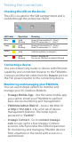
Testing the connection Checking the LED on the device The LED is located in the SIM compartment and is visible through the protective shield.
Important information Inseego Mobile App requirements Smartphone or device on iOS 13 or above, or Android 9.0 or above. System requirements Any device with Ethernet capability and an Internet browser. The FW2000e is compatible with the latest major operating systems and versions of Web browsers. Approved firmware versions This device will only operate with firmware versions that have been approved for use by your wireless carrier and the device manufacturer.