
User's Manual

Doc.: HD0389-00-Manuale_TL_GWCxxxx_r.0.1_EN.doc-00 17/04/2011 Page 30 of 49
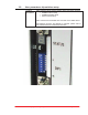
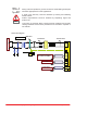
3.5.3. CN2: CanOpen connection #1
Can Bus CN2 is a PHOENIX mini-COMBICON 1803303 5-poles male
connector.
Please refer to software manual for further information about how
GWC device works when in CAN bus mode
Connection
table
Signal name Pin Function
0_CAN CN2.1 Can_Ground
CAN_L CN2.2 CAN_L signal
Earth CN2.3 Can_ Shield
CAN_H CN2.4 CAN_H signal
N.C. CN2.5 N.C.
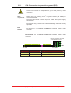
Wiring
requirements
Please use twisted wires having 0.5mm
2
(#20AWG) or 0.25mm
2
(#23AWG) section for CAN bus connection.
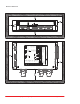
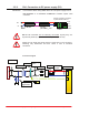
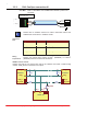
CANBus network schema
Please note that the 1st and the last node in the network must have a 120 ending
resistor. CAN_Ground connection is an option.
CAN_H
0_CAN
1 0_CAN
2 CAN_L
3 Earth
4 CAN_H
Phoenix mini-combicon 1803604
5-poles female 3.81m
5 N.C.
CAN_L
i
120R
CAN_H
CAN_L
CAN_Ground
CAN_V+
NODE #1
CAN_H
CAN_L
CAN_Ground
CAN_V+
CAN_H
CAN_L
CAN_Ground
CAN_V+
NODE #n
CAN_H
CAN_L
CAN_Ground
CAN_V+
CAN_H
CAN_L
CAN_Ground
CAN_V+
NODE #2
CAN_H
CAN_L
CAN_Ground
CAN_V+
100R
120R
100R
100R