
Installation and Operation Manual

3.30.22 357-00057-02 Rev A © Inovonics, 2022 - www.inovonics.com 2
2.4 Wear the Transmitter
The pendant transmitter is worn around the neck with the neck lanyard.
Caution: The neck lanyard included with the fall detect pendant is
designed with a breakaway feature for user safety. Substitution of a
stronger cord or chain may result in injury to the wearer.
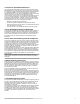
Neck Lanyard
To attach the neck lanyard:
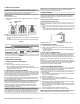
1. Secure the lanyard to the pendant’s attachment loop with a simple girth
hitch knot.
Figure 4 A simple girth hitch knot
2. Adjust the neck lanyard to the wearer’s neck size.
• Pull both slide adjustment tabs on the lanyard to reduce the length of
the cord.
• Pull both sides of the lanyard cord to increase the length of the cord.
Figure 5 Adjust the neck lanyard
3 Operate the Transmitter
3.1 Send a Resident-Initiated Alarm
To send an alarm:
1. Press the activation button for at least one second.
• When activated, the pendant will vibrate briefly and the red
transmission LED will blink rapidly for the first five seconds, and then
slowly until the alarm is cleared.
3.2 Generate an Automatic Fall Alarm
An automatic fall alarm is generated without a button activation based on a
proprietary algorithm using data from internal sensors. The algorithm takes
approximately 30 seconds to complete its calculations and transmit the fall
alarm. If a resident returns to their original position after a fall during that
30-second calculation period, no fall alarm will be sent.
When a fall alarm transmission is sent, the pendant will vibrate briefly and
the red transmission LED will blink rapidly for the first five seconds, and
then slowly until the alarm is cleared.
Note: The fall alarm message is processed by a cloud application and can
only be accessed through an active subscription to that service. Unless
there is an active subscription, the fall alarm will be transmitted as a
request for assistance in the same manner as a button press alarm to
ensure that a caregiver response is provided. However, it will not be
specifically identified as a fall event.
Caution: Residents should be instructed to always push the activation
button on their pendant to request assistance when they are able to do so,
even if fall detection is enabled. The automatic fall detection feature is an
enhancement to basic functionality and does not detect 100% of falls.
Note: The Inovonics fall detection solution may occasionally generate false
fall event alarms for reasons including, but not limited to, sudden air
pressure changes or purposeful movements.
3.3 Clear an Alarm
Note: After sending an alarm, an end user can send a subsequent alarm
once ten seconds have elapsed, even if the initial alarm has not been
cleared on the device. This is true whether the alarm is the result of a
button press or a fall event.
There are two ways to clear an alarm:
Using the Alarm Clearance Card
Note: The ACC680 alarm clearance card is an optional accessory sold
separately.
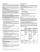
1. Place the dot on the ACC680 alarm clearance card over the activation
button.
• The red transmission LED will cease flashing and the blue alarm clear
LED will flash quickly six times to indicate the alarm has cleared.
Figure 6 Place the alarm clearance card over the activation button
Using a Button Press Pattern
1. Press the activation button three times, quickly.
2. When the blue LED flashes twice, press the activation button three
more times, quickly.
• The blue alarm clear LED will flash quickly six times to indicate the
alarm has cleared.
3.4 Coin Cell Low Battery Alert
When a low battery is detected, the transmitter will send a low battery alert,
and start a seven day countdown. If the battery has not been replaced
within two days from when the low battery alert message was sent, the
yellow low battery LED on the bottom of the pendant will begin to blink, and
will not stop until the battery is replaced, or the seven day countdown
expires.
If the seven day countdown expires without the battery being changed, a
high priority shutdown message will be sent to the application software and
the pendant will automatically go into storage mode. For more about
storage mode, see section 5, “Storage Mode”.
4 Coin Cell Battery Replacement
Note: Inovonics has tested and recommends Panasonic®, Maxell® and
FDK® (formerly Sanyo) CR2032 coin cell batteries.
The waterproof pendant uses one standard CR2032 coin cell battery. To
change the battery:
1. Use the ACC680 alarm clearance card or a quarter to turn the battery
door to the unlocked padlock icon.
2. Remove the battery door.
3. Remove the old battery from the battery compartment.
4. Place the new battery in the battery compartment, ensuring that the
positive terminal (+) faces up.
5. Seat the battery door over the battery so that the arrow on the battery
door is lined up with the unlocked padlock icon.
6. Use the ACC680 alarm clearance card or a quarter to turn the battery
door to line up the arrow on the battery door with the arrow under the
locked padlock icon.
7. Press the activation button to initalize the transmitter.
8. Clear the resulting alarm per section 3.3, “Clear an Alarm”.
Note: If the pendant is not activated after replacing the battery, the low
battery indication will not clear until the next check-in interval.
Cord
Attachment
loop
Tighten
Loosen