
Installation Instructions


11.1.19 357-05366-02 Rev A © Inovonics, 2019 - www.inovonics.com
EN1723 Dual Input Temperature Transmitter
Installation Instructions
1 Overview
The Inovonics EN1723 dual input temperature transmitter provides internal
measurement and external thermistor options in a single device. The on-
board sensor is excellent for monitoring ambient indoor temperature, and
the external sensor is user selectable to match your application.
1.1 Inovonics Contact Information
If you have any problems with this procedure, contact Inovonics Wireless
technical services:
• E-mail: support@inovonics.com.
• Phone: (800) 782-2709.
1.2 Dual Input Temperature Transmitter Internal
Components
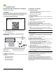
Figure 1 Dual input temperature transmitter internal components
1.3 What’s In The Carton
The following are included with individual units only; they are not included
in bulk sales.
• Three wall mount screws.
• Three wall mount anchors.
• Two selection jumpers.
• One piece mounting tape.
• One 3.0V lithium battery.
2 Installation and Startup
2.1 Installation Notes
• These products are designed to be installed and maintained by
professional security technicians.
• Products are intended for indoor use.
• Manually test all products weekly.
2.2 Install the Battery
1. Pry the top lip of the mounting bracket up, and lift the bracket off of the
transmitter.
2. Use your thumb to depress the housing release tab on the bottom of the
transmitter; separate the housing.
3. Install the battery.
4. Press the reset button to initialize the transmitter.
2.3 Mount an External Thermistor
The transmitter uses an on-board thermistor. If you are not using an
external thermistor, skip to section 2.4, “Select the Frequency Band”; if you
are using an external thermistor:
1. Wire the external thermistor using 24-gauge wire, no more than 40 feet
long.
2. Route the external thermistor wiring through either the rectangular
cutouts on the back of the housing and bracket, or through the rounded
wiring cutout at the top of the housing.
Note: If you want to use the cutout at the top of the housing, you will need to trim the
bracket.
3. Use a small screwdriver to attach the external thermistor wiring leads to
the terminal block.
4. Place a jumper on the external thermistor selection pins, allowing the
transmitter to use the external thermistor in addition to the on-board
thermistor.
5. Press the reset button to complete configuration.
2.4 Select the Frequency Band
EchoStream products are able to use a range of radio frequencies, and is
shipped from Inovonics set for your geographic area.
• The jumper will be set on on the two pins marked NZ to set the
frequency range to 921-928 MHz for New Zealand.
• The jumper will be set on the two pins marked AU to set the frequency
range to 915-928 MHz for Australia.
• The jumper will be removed to set the frequency band to 902-928
MHz for North America.
1. Ensure the frequency band is set for your geographic are.
2. If the frequency band is not set for your geographic area, place a
selection jumper on the appropriate frequency band selection pins to
select Australia or New Zealand, or remove it for North America.
3. If you have changed the frequency band, press the reset button to
complete configuration.
Caution: When pressing the reset button, make sure you don’t also touch
the frequency band selection pins. Touching the frequency band selection
pins while pressing the reset button can inadvertently set the single input
universal transmitter to the wrong frequency band.
2.5 Program the Transmitter
EN1723 transmitters are programmed at the factory. It is not usually
necessary to reprogram EN1723 transmitters. If you want to reprogram the
transmission interval, temperature measurement interval and/or
temperature units, the parameters can be changed using the programming
header and the ACC17XX programming cable. Contact Inovonics technical
services for details.
For product and installation videos visit us at
www.inovonics.com/videos or use the QR
code below.
A Terminal block B External thermistor selection pins
C Reset button D Frequency band selection pins
E Programming header
B
C
E
D
A